© 2005 PAT GmbH · D-76275 Ettlingen · Hertzstr. 32 - 34 · ++49 (0) 7243 709-0 · FAX ++49 (0) 7243 709-222 · Email: pat.ettlingen@pat-group.net 3
24 160 19_0106E_Rev D.doc / 2005-06-27 / rk.
3. SYSTEM DESCRIPTION
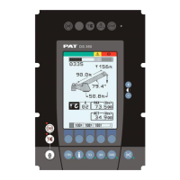
The PAT Load Moment Indicator DS 160 consists of a central microprocessor unit, operating console,
length/angle sensor, pressure transducers, and anti-two block switches.
The system operates on the principle of reference/real comparison. The real value, resulting from the load
measurement is compared with the reference data, stored in the central processor memory and evaluated in the
microprocessor. When limits are reached, an overload warning signal is generated at the operator’s console. At
the same time, the crane functions, such as hoist up and boom down, will be stopped.
The fixed data regarding the crane, such as capacity charts, boom weights, centers of gravity and dimensions
are stored in memory chips in the central processor unit. This data is the reference information used to calculate
the operating conditions.
The length/angle sensors inside the cable reel, which is mounted on the boom, measure the boom length and
angle. The boom length is measured by the cable reel cable that also serves as an electrical conductor for the
anti two-block switches.
The crane load is measured by pressure transducers attached to the piston and rod sides of the hoist cylinders.
c
d
e
f
g
1. A2B Switch(-es)
2. Pressure Transducers
3. Cable Reel
4. Console
5. Central Unit (in cab or outside)
Fig. 1: Components of the LMI
System PAT DS 160