Do you have a question about the Hirschmann qSCALE maestro and is the answer not in the manual?
Lists components for base kits with vScale D2 or D3.
Details the components of the qSCALE maestro junction box.
Lists components included in the pressure sensor kit.
Details components for the boom upgrade kit.
Lists components for the light tower indicator kit.
Explains the purpose and location of the device's type plate.
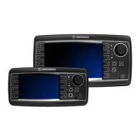
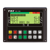
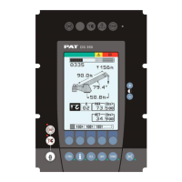
Illustrates and labels the console's buttons and display components.
Describes the meaning of various indicator lights and displays.
Details the procedure for entering service, daily, or LMI passwords.
Explains how to find and convert the daily password seed.
Outlines the navigation path to system settings.
Introduces sensor calibration and required passwords.
Guides through calibrating the boom angle sensor.
Guides through calibrating the boom length sensor.
Explains how to adjust lift cylinder data for accurate load display.
Details the process for inputting numerical measurements during calibration.
Explains how to adjust the alarm volume settings.
Describes how to load machine models and load charts via USB.
Details downloading stored event records to a USB drive.
Explains how to reset the system's operating hour meter.
Covers taking and saving screenshots.
Describes methods for capturing the current screen display.
Explains saving screen captures to USB drive or internal memory.
Provides guidelines for cleaning, usage, and repair of the console.
Categorizes common problems and directs users to relevant sections.
Lists steps for performing a basic system inspection.
Explains the meaning of LED indicators on control units and consoles.
Defines the LED indicators on the central control unit.
Refers to another section for console indicator definitions.
Explains how the boom angle sensor works and basic troubleshooting.
Explains how the boom length sensor works and basic troubleshooting.
Describes how pressure sensors work and initial checks.
Explains how load is calculated and factors affecting it.
Describes the A2B switch function and its wiring.
Provides a flowchart for troubleshooting A2B switch input issues.
Explains CAN bus protocol and its role in the system.
Explains how to check sensor status via console screens.
Details how to interpret CAN bus sensor readings on the console.
Explains how to check digital input status on the console.
Explains how to check digital output status on the console.
Lists the technical specifications of the qSCALE maestro system.
Shows the detailed wiring connections for the junction box.
Presents dimensional drawings for the vSCALE D2 console.
Presents dimensional drawings for the vSCALE D3 console.
Lists error codes and their general meanings.
| Brand | Hirschmann |
|---|---|
| Model | qSCALE maestro |
| Category | Touch Panel |
| Language | English |