Do you have a question about the Hirschmann PAT IFLEX5 and is the answer not in the manual?
Explains the core operations of the iFLEX5 Load Moment Indicator.
Details the Controller Area Network communication protocol used.
Describes each component within the iFLEX5 system.
Addresses issues like blank screens, error codes, and display anomalies.
Helps resolve situations where sensor data is inaccurate or mismatched.
Step-by-step guide for diagnosing and fixing angle sensing errors.
Step-by-step guide for diagnosing and fixing length sensing errors.
Step-by-step guide for diagnosing and fixing pressure sensing errors.
Step-by-step guide for diagnosing and fixing slewing sensing errors.
Step-by-step guide for diagnosing and fixing load sensing errors.
Specific troubleshooting for E61 CAN bus data transfer errors.
Defines key terms and concepts for the BCS.
Lists and describes the main components of the BCS.
Explains the operation of manual and automatic modes within the BCS.
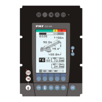
Labeled diagram identifying key PAT iFLEX5 LMI components.
A high-level block diagram illustrating system connectivity.
Wiring diagram for the central unit to crane and console interface.
Specific wiring diagram for the length/angle sensor cable reel.
Wiring diagram for the boom extension anti-two-block system.
Details the 70-pin connector layout for the main central unit.
Wiring diagram for the central unit's crane interface.
Wiring diagram illustrating console and sensor connections.
Wiring diagram for the LG152 cable reel assembly.
Wiring diagram for the luffing extension system connections.
Part numbers and descriptions for the central unit assembly.
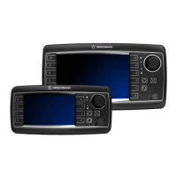
Part numbers and descriptions for the vertical graphic console.
Part numbers and descriptions for an alternative console assembly.
Part numbers and descriptions for the LWG508 cable reel.
Part numbers and descriptions for the LWG521 cable reel.
Part numbers and descriptions for the LWG152 cable reel.
Identifies the part number for the pressure transducer block.
Identifies the part number for the 11-meter cable assembly.
Identifies the part number for the standard wiring harness.
Identifies the part number for the boom control wiring harness.
Identifies the part number for the 14-meter cable assembly.
Identifies the part number for the radio wind speed kit.
Steps to access the calibration function on the console.
Procedure to set the zero point for pressure transducer inputs.
Procedure to set the zero point for the slew potentiometer.
Steps to calibrate the length sensor's zero and full range.
Specific adjustment for the LWG508 cable reel length potentiometer.
Detailed sequence for adjusting the length sensor calibration.
Procedure for replacing the length sensor cable within the cable reel.
Steps to calibrate the angle sensor using an inclinometer.
Steps to set the zero point for the slew potentiometer.
Explains initial error codes related to ranges and zones.
Explains error codes related to sensor limits and overload checks.
Explains error codes related to angle, length, and slewing sensors.
Explains error codes related to exceeding upper limit values.
Explains system program, memory, and data file errors.
Explains CAN bus communication and sensor data transfer errors.
Explains errors related to slewing, boom control, and rigging conditions.
Explains errors related to console communication and power supply.
Explains errors related to console files, A2B circuits, and prohibited areas.
Explains datalogger, battery, and watchdog timer errors.
Details common sources of water entry and how to prevent them.
Addresses condensation within enclosures and methods for mitigation.
| Brand | Hirschmann |
|---|---|
| Model | PAT IFLEX5 |
| Category | Touch Panel |
| Language | English |