Angle Sensing
© Hirschmann Rev. I 05/22/17 190154_I.DOC
5 ANGLE SENSING
The System measures the angle of the main boom of the machine with an angle sensor. The angle
sensor is contained within the cable reel, located on the left side of the main boom.
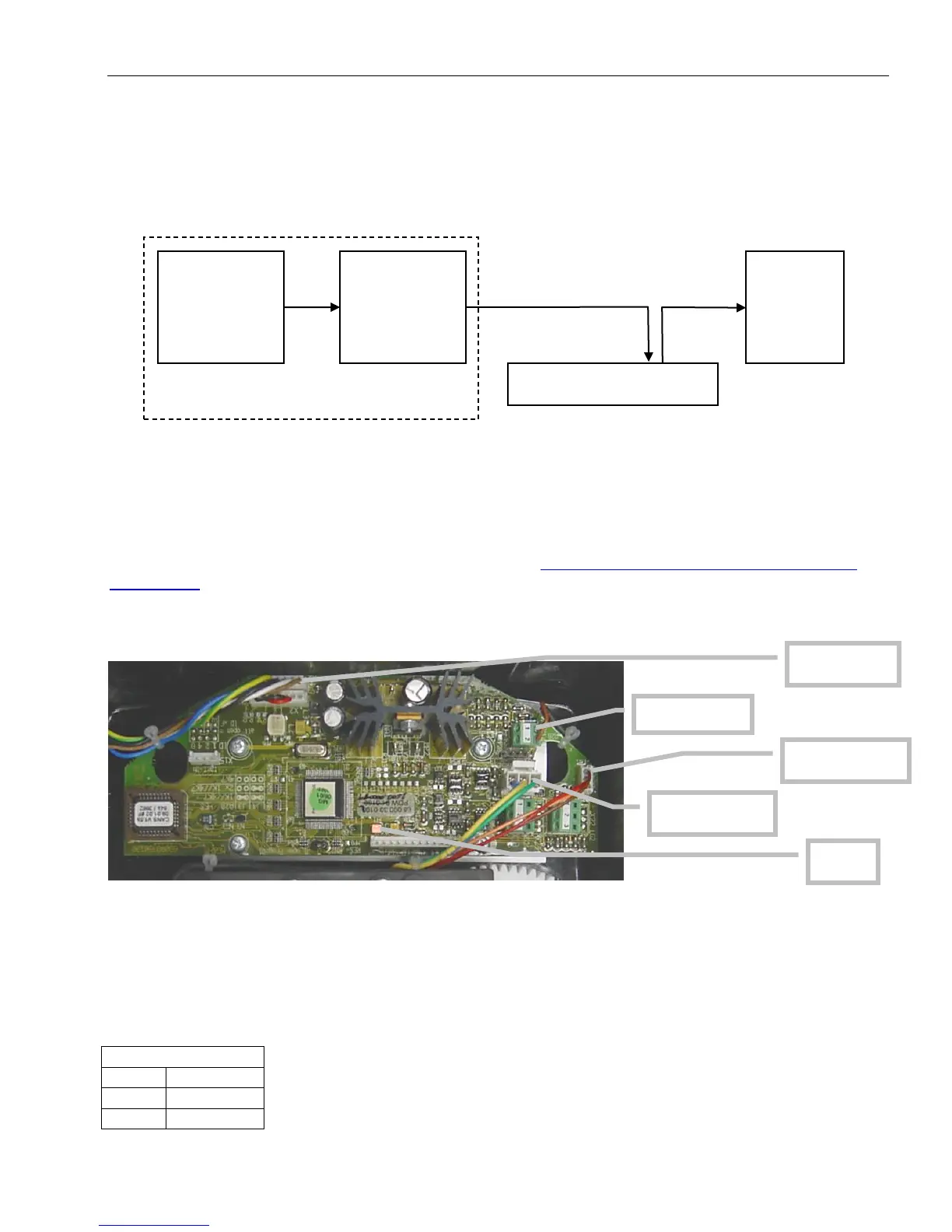
Block Diagram
The signal runs from the angle sensor to the Can-Bus converter board, both located in the cable reel.
From there, it travels as digital information on the CAN-Bus to the pressure transducer, which acts as
a T-connector to the main CAN-Bus running to the central unit.
So, what do you do when you are having a problem with your angle read-out?
Start by verifying the angle display. Refer to the section “Troubleshooting A Sensor Problem Using
The Display” to call up the sensor signal on your console display. The CAN-Bus is digital and as such
will either transmit the signal correctly or not at all. If your readings are off, you have to determine
what is causing the problem (reference the following flow charts).
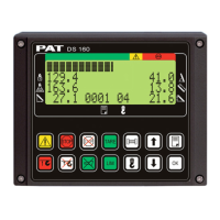
CAN-Bus electronics in cable reel.
The angle sensor has a potentiometer built in that is driven by a pendulum. As the angle changes, so
will the pendulum and with it the potentiometer’s axle. The converter board supplies a constant
voltage of 5V to the angle sensor and in return monitors the voltage of the potentiometer. The terminal
used is X21. The angle sensor is connected as follows: