30
PowerMICE
Release
01
04/2014
2.2.8 Connecting the terminal blocks for supply voltage
and signal contact
The supply voltage and the signal contacts are connected via a 4-pin terminal
block and a redundant 4-pin terminal block. Secure the terminal blocks by the
supplied z-section sheet and M2.5 screw inclusive tooth washer.
Supply voltage
Redundant power supplies can be used. Both inputs are uncoupled.
There is no distributed load. With redundant supply, the power supply unit
supplies the device only with the higher output voltage. The supply
voltage is electrically isolated from the housing.
Note: With non-redundant supply of the mains voltage, the device reports
a power failure. You can prevent this message by applying the supply
voltage via both inputs, or by changing the configuration in the
Management.
Signal contact
The signal contact monitors proper functioning of the device, thus
enabling remote diagnostics. You can specify the type of function
monitoring in the Management.
You can also use the switch Web page to switch the signal contact
manually and thus control external devices.
A break in contact is used to report the following conditions via the
potential-free signal contact (relay contact, closed circuit):
The detected inoperability of at least one of the two voltage supplies
(voltage supply 1 or 2 is below the threshold value).
A continuous malfunction in the device (internal supply voltage).
The defective link status of at least one port with active link monitoring.
In the delivery state, link status monitoring is deactivated.
An error during the self-test.
Incorrect configuration of the HIPER-Ring or ring coupling.
The temperature threshold has been exceeded or has not been
reached.
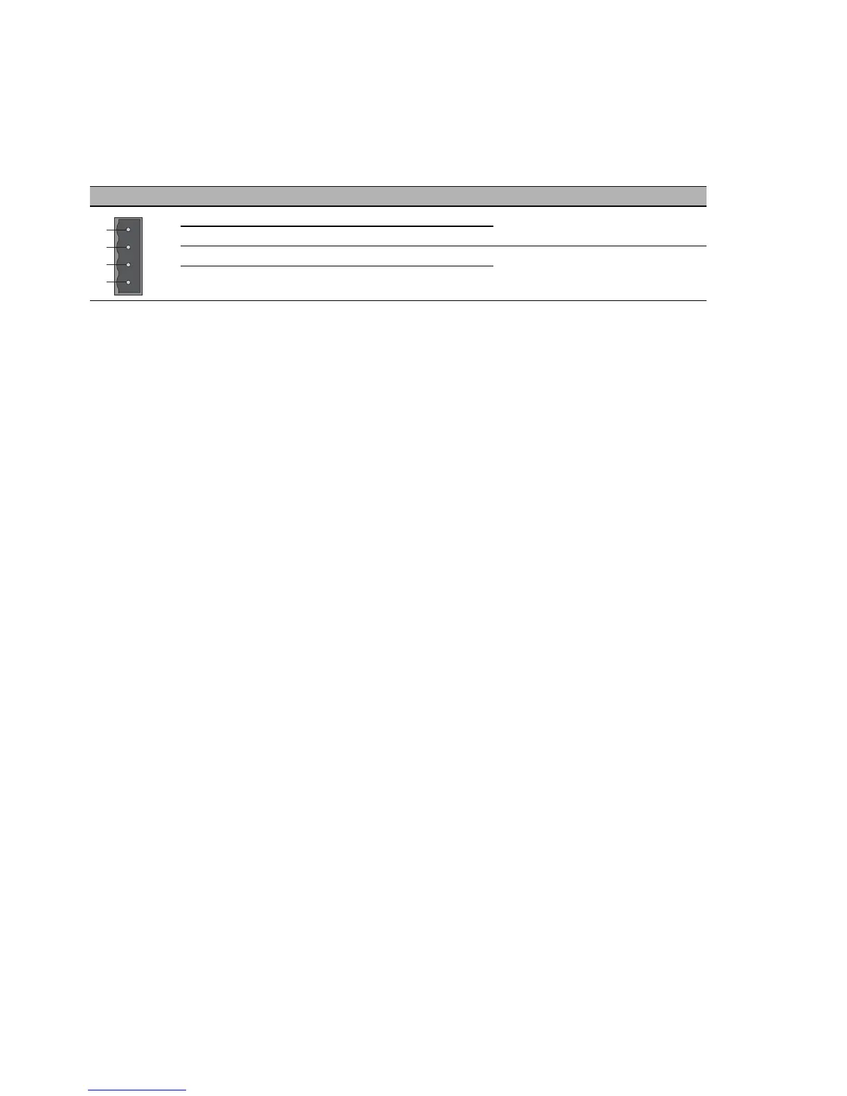
Figure Pin Assignment Rated voltage range DC
1 + 24 V 18.0 V to 32.0 V
20 V
3 Signal contact
4 Signal contact
Table 5: Pin assignment of the 4-pin terminal block
 Loading...