continuity. If the continuity is faulty at any point,
replace the switch.
NOTE:
• When the power supply is opened, should the
multimeter gear to 200 Ω,digital watch LCD
display。
A about 4.4±0.3Ωin normal operations
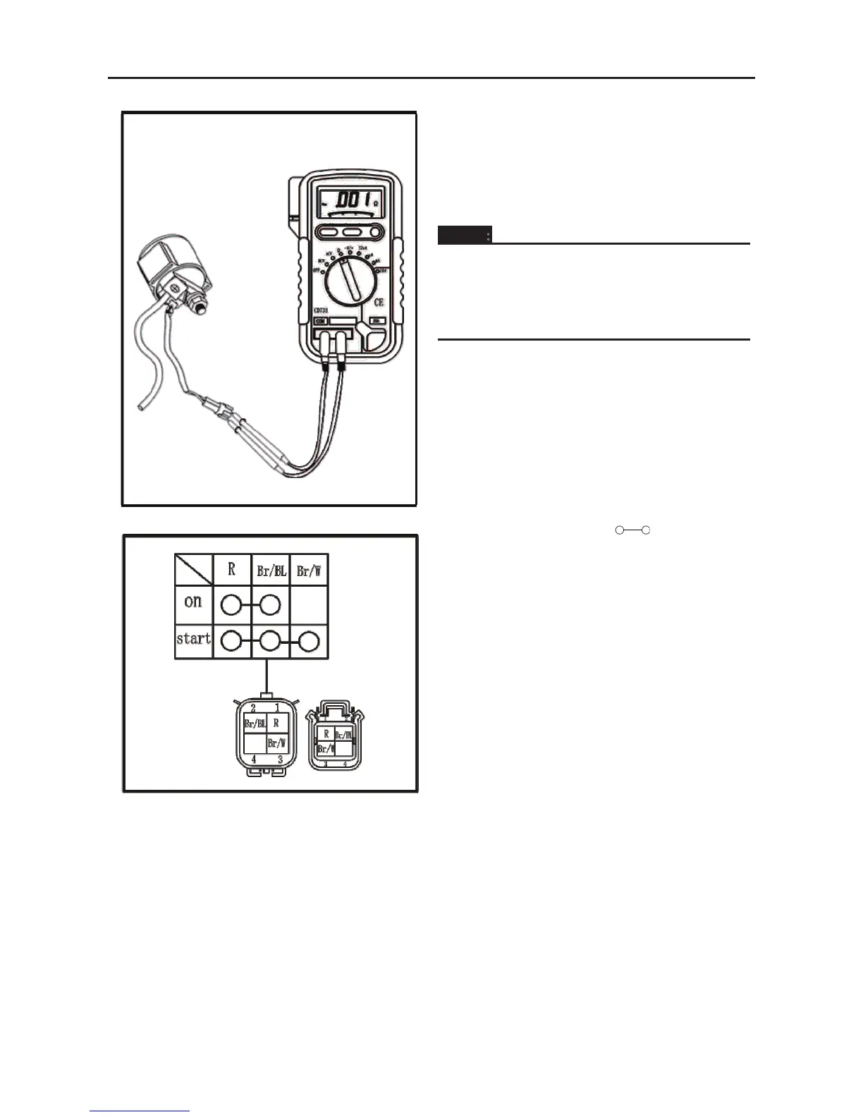
The terminal connections for switches (main
switch, light switch, etc.) are shown in a chart
similar to the one on the left. This chart shows the
switch positions in the column and the switch lead
colors in the top row.
For each switch position, “ ” indicates the
terminals with continuity.
The example chart shows that:
①There is continuity between the “Red and
Brown/Blue” leads when the switch is set to
“ON”.