--- 20 ---
(2) Adjustment of the lower limit position of the saw blade
The saw blade lower limit position must be adjusted so that the cutting edge of the saw blade (or dummy disc)
is 41 mm to 42 mm below the upper surface of the Base [49]. To perform the adjustment, loosen the Lock Nut
M8 [105] and turn the Bolt M8 x 25 [106]. By turning the Bolt M8 x 25 [106] counterclockwise, the saw blade
lower limit is raised. By turning the Bolt M8 x 25 [106] clockwise, the saw blade lower limit is lowered.
On completion of the adjustment, ensure that the Lock Nut M8 [105] is properly tightened.
[CAUTION] Before tightening the Lock Nut M8 [105], check that the saw blade does not contact the Turn
Table [38].
11-5. No-load Current
After no-load operation for 30 minutes, the no-load current values should be as follows.
11-6. Reassembly Requiring Adjustment
(1) Adjustment of squareness between the saw blade (dummy disc) and the fences
Voltage, frequency
No-load current
110 V, 115 V
8 A max.
220 V, 230 V, 240 V
4 A max.
After disassembly or replacement of the Base [49], Turn
Table [38], Fence (A) [46], Fence (B) [31] or Hinge [7], it is
necessary to perform necessary adjustment to ensure that
the fences are positioned at precise right angles with
relation to the saw blade (or dummy disc). Align fence (B)
with the saw blade (or dummy disc), and adjust them as
necessary to ensure squareness (tolerance: 0.15/100 mm).
As shown in Fig. 23, use a square to adjust fence (B) so
that it is square with the saw blade. Next, use a straight
edge to adjust fence (A) so that it is exactly aligned with
fence (B). Finally, use the square to confirm squareness of
fence (A) with the saw blade (tolerance: 0.15/100 mm).
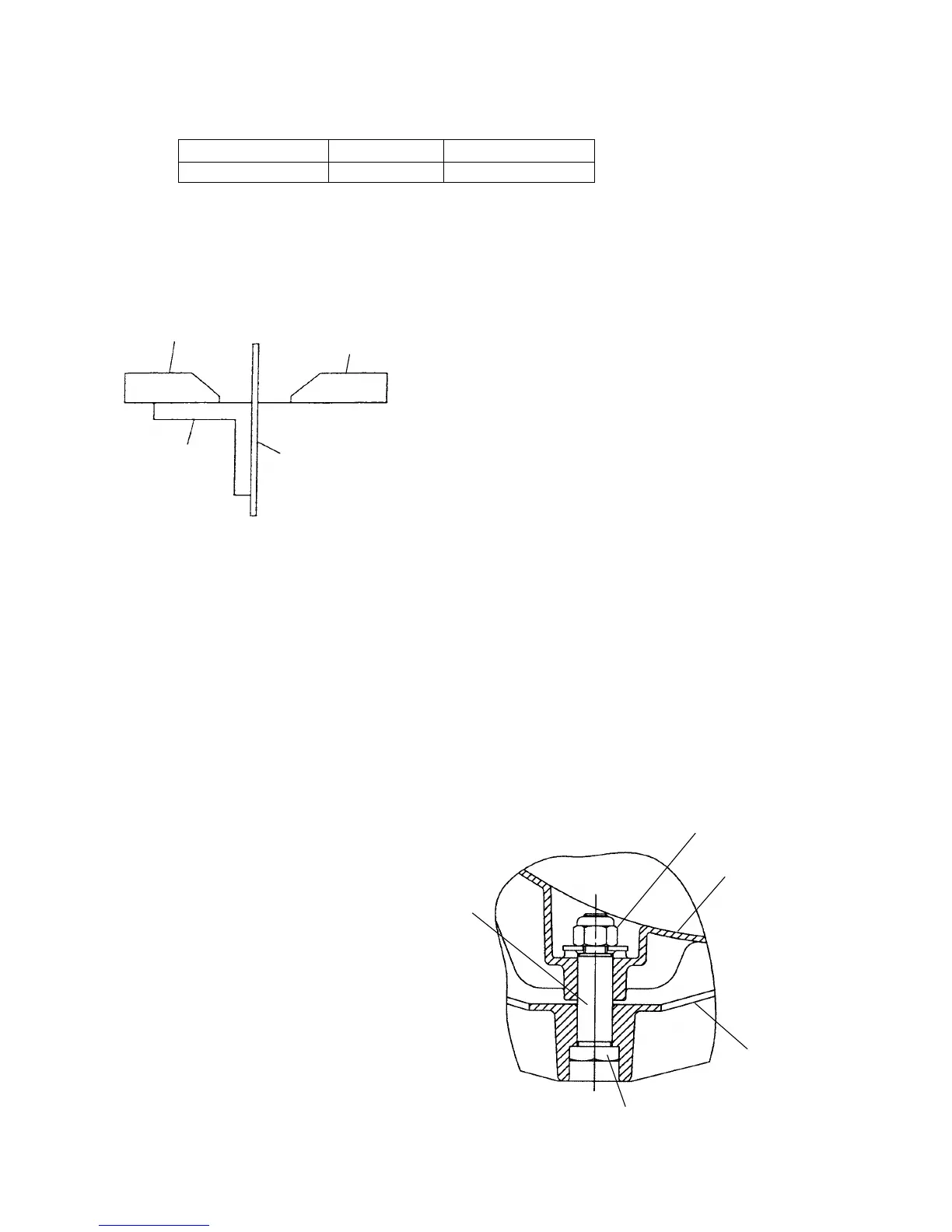
(3) Reassembly of the Turn Table [38]
When reassembling the Turn Table [38] and the
Base [49], tighten the Nylon Nut M8 [32] so that
the Turn Table [38] turns smoothly without
excessive play or vibration. During reassembly,
liberally apply grease (Hitachi Motor Grease
No. 29, Code No. 930035 is recommended) at the
point marked "A" in Fig. 24.
Fig. 24
Nylon Nut M8 [32]
A
Shaft (B) [53]
Base [49]
Turn Table [38]
Square
Fig. 23
Saw blade or
dummy disc
Fence (A)
Fence (B)

 Loading...