--- 15 ---
For miter cut setting
If the turn table has been set to either of the angles described, move the turn table adjusting side handle a
little to the right and left to stabilize the position and to properly align the miter scale and the tip of the
indicator before the operation starts.
For bevel cut setting
Move handle on miter section to the right and left and check that the position is stable and the angle scale
and the tip of the indicator are properly aligned. Then tighten the clamp lever.
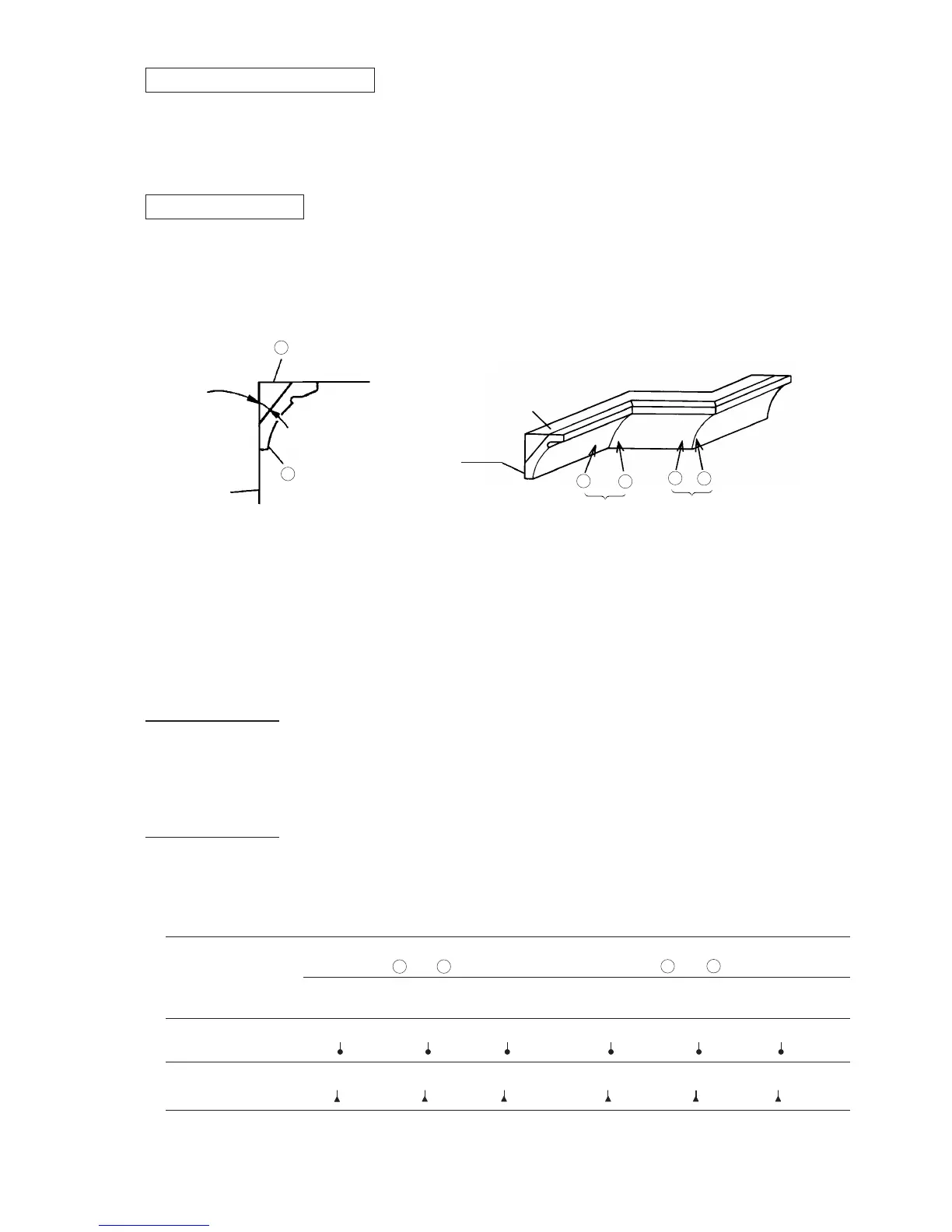
(8) Crown molding cutting
This machine can cut two types of crown molding workpieces by combining the miter and bevel cutting
operations (for USA).
Figure 13 shows two common crown molding types having angles of (θ) 38û and 45û. For the typical crown
molding fittings, see Fig. 14.
(7) Compound (miter + bevel) cutting
Compound cutting can be accomplished by combining the miter cutting and bevel cutting operations described
in paragraphs (4) and (5) above. (For details, please refer to the Instruction Manual.) When the saw blade
section (head) is inclined 45û to the left, the table can be turned up to 45û to the right and left.
The table below shows the miter angle and the bevel angle settings that are ideal for the two crown molding
types.
NOTE: For convenience, positive stops are provided for both the miter setting and the bevel setting
(left and right 31.6û) positions.
Type of
crown molding
To process crown molding at
positions and in Fig. 14
To process crown molding at
positions and in Fig. 14
Miter angle
setting
Bevel angle
setting
Miter angle
setting
Bevel angle
setting
Right 30û
( mark)
Right 35.3û
( mark)
Left 30û
( mark)
Right 30û
( mark)
Left 35.3û
( mark)
Left 30û
( mark)
45û type
Right 31.6û
( mark)
Left 33.9û
( mark)
Right 33.9û
( mark)
Left 31.6û
( mark)
Left 33.9û
( mark)
38û type
3
1 4
2
Right 33.9û
( mark)
Table 3
Upper surface ceiling
Wall
Lower surface
Fig. 13 Fig. 14
Outside corner
Ceiling
Wall
Inside corner
A
B
2
3
θû
4
1
 Loading...