1. Front Panel
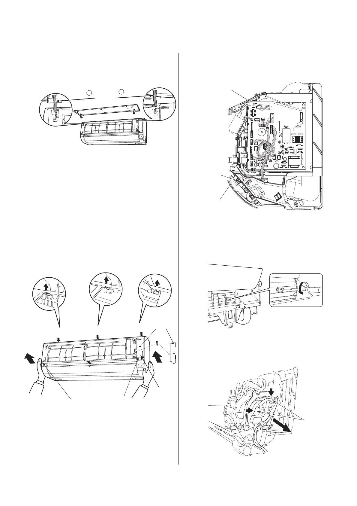
2. Front cover
(2)After removing two screws, pull the center of
the front cover forward and release the claws
.
( )Hold the front cover at both lower sides and
pull them forward to remove.
Fig. 2
3. Control P.W.B. and Indicating
P.W.B.
(1)Remove each connector from the lead wire.
(2)Remove the four P.W.B. supports from the
control P.W.B.
(3)Pull the support hook at the upper side of the
indication lamp of the indicating P.W.B. and pull
out the P.W.B. forward.
Fig. 3
Fig. 4
Fig. 5
Procedure for Disassembly and Reassembly
INDOOR UNIT
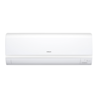
Be sure to hold the front panel with both hands to
detach and attach it.
3
Fig. 1
(1)After removing the screw of fix ing the
terminal cover, hold the handle of terminal
cover and remove it.
Indicating P.W.B.
C
ontrol P.W.B.
Support hook
RAK-15QEF,RAK-18/25/35/50REF
RAK-25/35/50REFC
1
2
Push
Arm
S
Claw
Claw
Claw
Claw
Claw
crew
S
crew
Screw
cover
Terminal
cover
angential air flow fan and fan motor
(1)Loosen the fan lock screw.
(2)Press the fan motor cover 2 fixed pawl, and
remove from the right to.
1.
Push the end of the right-side arm outward to release
the tab.
2.
Move the left-side arm outward to release the left tab,
and then pull the panel towards you.
 Loading...