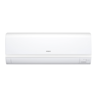
The temporary switch is used to operate the air conditioner temporarily when the wireless remote control
is lost or faulty.
The air conditioner operates in the previous mode at the previously set temperature. However, when the
power switch is set to OFF, it starts automatic operation.
Fig. 7-1
TEMPORARY SW
MICROCOMPUTER
R405
SW211
Temporary
switch
0V
0V
C405
R663
5V
7. Temporary Switch Circuit
R403
5V
R406
C404
90
1
2
3
4
5
0
0 10 20 30 40
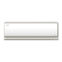
8. Room Temperature Thermistor Circuit
A room temperature thermistor circuit is shown in Fig. 8-1.
According to room temperature, the voltage of point becomes as it is shown in Fig.8-2.
Microcomputer
Room Temperature
Thermistor
Voltage of point (V)
(
㷄
)
Room temperature
Room
temperature input
Fig. 8-1
Fig. 8-2
䃢
A
0V
0V
5V
2
0
1
010203040
3
4
5
-10
R402
C403
R407
91
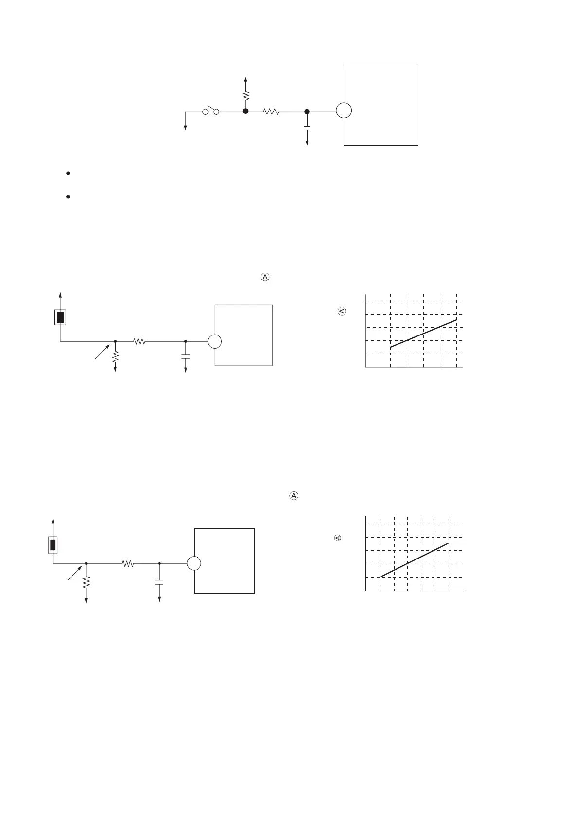
9. Heat Exchanger Thermistor Circuit
Heat exchanger temperature is noticed inside the room
(1) Preheating
(2) Low-temperature defrosts at cooling and dehumidification operation time.
(3) Not working of reversing valve or detection of opening of heat exchanger thermistor is controlled.
According to heat exchanger temperature, the voltage of point becomes as it is shown in Fig. 9-2.
Heat exchanger
thermistor
Microcomputer
Heat exchanger
input
Fig. 9-1
Fig. 9-2
Voltage of point (V)
㷄
Heat temperature ( )
䃢
A
100
0V
0V
 Loading...