EasyManuals Logo

Hitachi RCUE100AG2 User Manual

Hitachi RCUE100AG2
182 pages
To Next Page IconTo Next Page
To Previous Page IconTo Previous Page
Page #169 background imageLoading...
Page #169 background image
SMGB0003 rev.0 - 11/2006
pag. 167
Maintenance
6
6
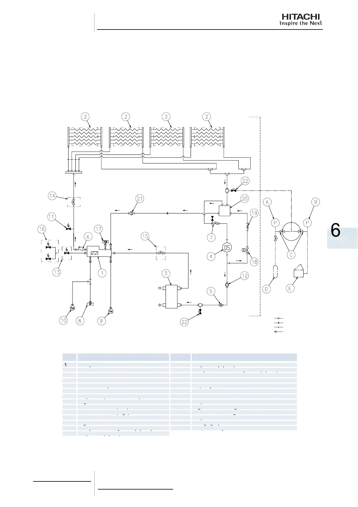
6.8.2. Refrigerant Cycle Diagram of Hitachi Air-Cooled Water Chiller
(RCUE 80, 160, 240, 320, 400 AG2) with economizer.
No. Name No. Name
1
Compressor
Compressor
15
Stop Valve (Option)
Stop Valve (Option)
2
Air Cooled Condenser
16
Compressor Dual Safety Valve (Option)
3
Water Cooler
17
Pressure Switch
4
Filter Drier
18
Solenoid Valve
5
Electronic Expansion Valve
19
Capillary Tube
Capillary Tube
6
Check Valve
20
Economizer
7
Stop Valve (with check Joint)
21
Strainer
8
High Pressure Switch
22
Stop Valve
Stop Valve
9
Pressure Sensor (Low)
A
High Pressure Gauge
High Pressure Gauge
10
Pressure Sensor (High)
B
Low Pressure Gauge
Low Pressure Gauge
11
Pressure Relief Valve
C
Stop Valve
Stop Valve
12
Sight Glass
Sight Glass
D
Charging Cylinder
Charging Cylinder
13
Compressor Safety Valve (Option)
E
Vacuum Pump
Vacuum Pump
14
Stop Valve (Option)
Stop Valve (Option)
R407C shall be charged by LIQUID.
NOTE:
Option
Option
Option
Option
Gauge
manifold
Charging
Charging
Evacuation
Unit side
Flange Connection
Flare Connection
Solder Connection
Refrigerant Cycle
Chilled Water Inlet
Chilled Water Outlet

Table of Contents

Questions and Answers:

Question and Answer IconNeed help?

Do you have a question about the Hitachi RCUE100AG2 and is the answer not in the manual?

Hitachi RCUE100AG2 Specifications

General IconGeneral
BrandHitachi
ModelRCUE100AG2
CategoryChiller
LanguageEnglish

Related product manuals