Perform the work according to “Dissolution and Composition Manual of Hitachi Half Sealed
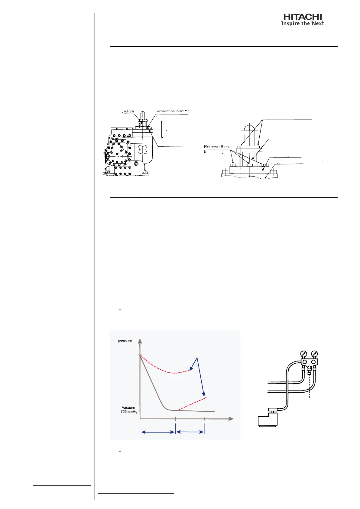
When compressor is removed from refrigeration cycle, high pressure part should be separated
between projecting part fl ange of compressor and upper cover of oil separator. Do not
be separated between check valve and projecting part fl ange of compressor, or collected
6.10. Vacuuming Procedure
6.10. Vacuuming Procedure
6.10. Vacuuming Procedure
Although refrigerant is collected to airside heat exchanger by the above collection operation,
it is necessary to be vacuumed due to that refrigerant cycle of low pressure side pipe and of
water side heat exchanger are open.
Vacuum should be performed in the following 2 positions.
Stop valve for refrigerant insertion ((D) part)
Check joint of compressor suction side ((E) part)
*Capillary for compound gauge in low pressure side is installed in check joint. This
capillary should be removed from check joint.
Vacuuming procedure is shown in the following.
Manifold valve, vacuuming pump and vacuuming gauge for R407C are connected.
Operate vacuuming pump for at least 1~2 hours until vacuum grade be below
Vacuum gauge should be used to measure a target vacuum, however, it is
impossible to read the vacuum gauge installed in the manifold very accurately.
It is recommended to use a digital vacuum measure device, available in the
Projecting part fl ange of
Projecting part fl ange of
Projecting part fl ange of
Do not remove these bolts
or refrigerant is ejected
or refrigerant is ejected
Projecting part fl ange of compressor
Projecting part fl ange of compressor
Projecting part fl ange of compressor
Projecting part fl ange of compressor
Upper cover of oil separator
Upper cover of oil separator
Upper cover of oil separator
Upper cover of oil separator
Upper cover of oil separator
Upper cover of oil separator
 Loading...