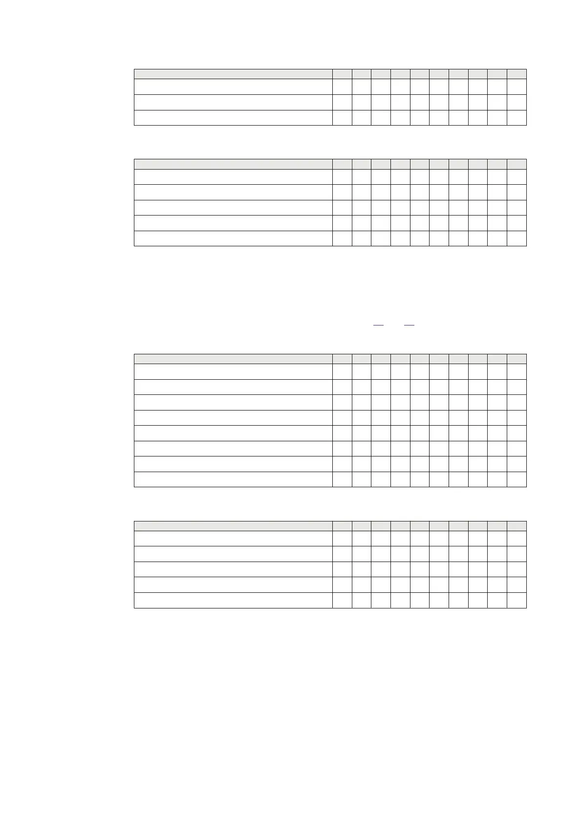
INPut
LOCTRL1 X
LOCTRL2 X
LOCTRL3 X
Table 43: Activate output signals if OpMode = 2 Out Of 2
OUTPut
Non X X
TRIP X X X X X
TRL1 X
TRL2 X
TRL3 X
7. Connect the trip output to a timer.
8. Have inputs CR1and CR2 activated. Start the timer from activation of input LOCTR and stop
the timer from TRIP output.
9. Check the trip time.
If OpMode = 1 Out Of 2:
10. Activate input and check output signals according to table
44 and 45.
Table 44: Activate input signals if OpMode = 1 Out Of 2
INPut
CR1 X X X X X
CHERR1 X
CR2 X X X X X X
CHERR2
LOCTR X X X
LOCTRL1 X X
LOCTRL2 X X
LOCTRL3 X X
Table 45: Activate output signals if OpMode = 1 Out Of 2
OUTPut
Non X
TRIP X X X X X X X X X
TRL1 X X
TRL2 X X
TRL3 X X
11. Connect the trip output to a timer.
12. Have inputs CR1 and CR2 activated. Start the timer from activation from activation of input
LOCTR and stop the timer from TRIP output.
13. Check the trip time.
Completing the test
Continue to test another function or end the test by changing the TESTMODE setting to Off. Restore
connections and settings to the original values, if changed for testing purposes.
Section 11 1MRK 505 378-UEN Rev. K
Testing functionality by secondary injection
230 Line differential protection RED670
Commissioning manual
© 2017 - 2022 Hitachi Energy. All rights reserved



 To Next Page