1.1. Select the port.
1.2. Set values for Mode, IPAddress and IPMask. Mode must be set to Normal.
1.3. Check that the correct IP address is assigned to the port.
2. Set the TCP communication parameters by navigating to: Main menu /Configuration /
Communication /Station communication /phasor measurement /PMU Configuration /
PMUCONF . The first three parameters are related to TCP communication. The default TCP
parameters setting can be used. More information regarding TCP communication is available in
the Application manual under section Short guidance for use of TCP.
3. Set the UDP communication parameters by navigating to: Main menu /Configuration /
Communication /Station communication /phasor measurement /PMU Configuration /
PMUCONF . The first three parameters are related to TCP communication and the rest of
parameters are related to setting of six independent UDP client groups. Each UDP group has
eight parameters. More information regarding UDP communication is available in the
Application manual under section Short guidance for use of UDP. The following steps
describes setting parameters for the first UDP group:
3.1. Enable the first UDP group by setting the parameter SendDataUDP1 to On.
3.2. Set the UDP client IP address by setting the parameter UDPDestAddres1 to
192.168.1.99. For the purpose of the communication set-up in this section the LAN IP
address of the PC is used, where the PDC client tool is installed.
3.3. The default parameter settings can be used for the rest of parameters for the first UDP
group.
9.4 Setting the TCP/UDP client communication
GUID-6CEE3261-D211-4051-8CA8-5840C27C560E v2
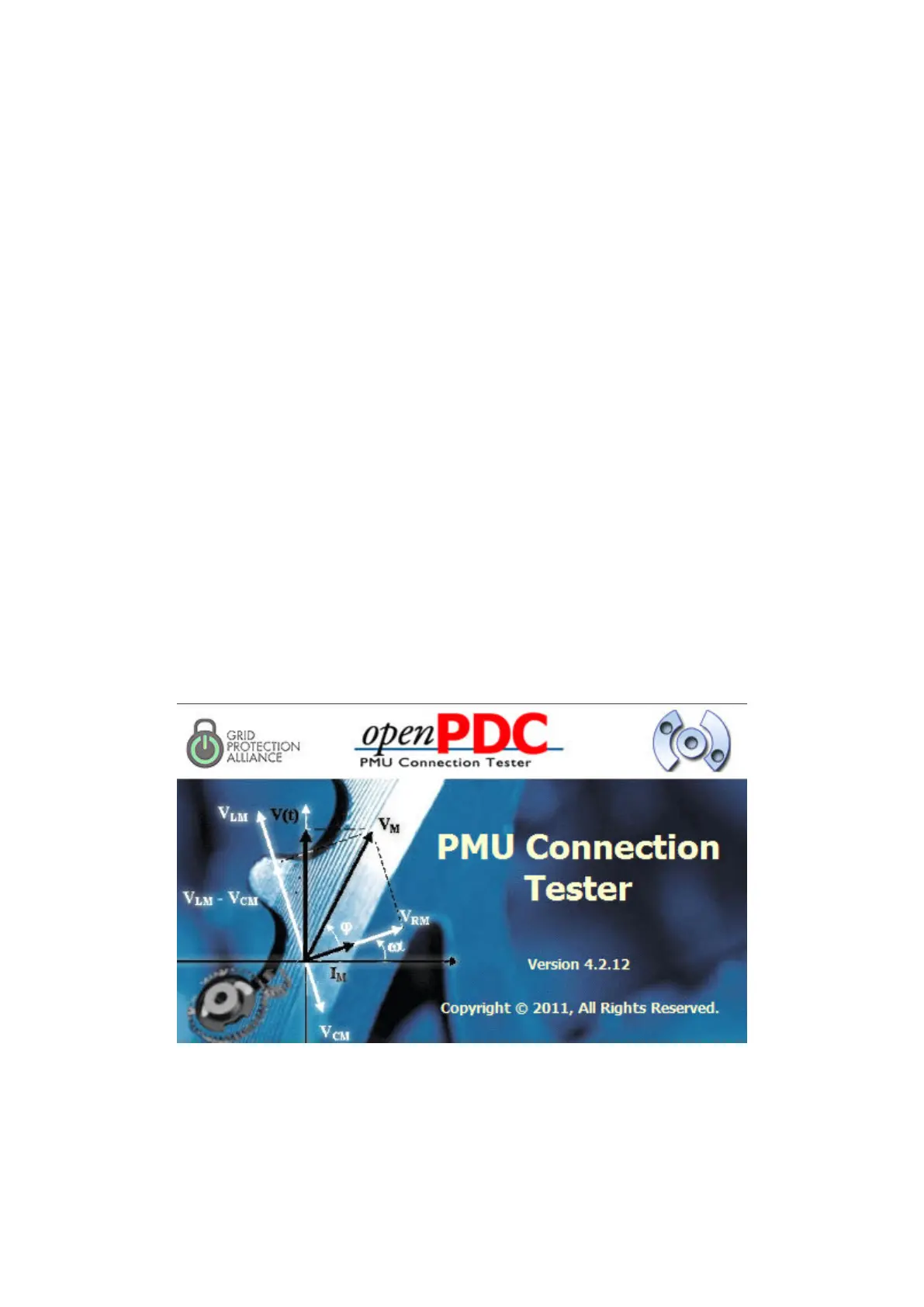
As an example of a TCP/UDP client, the openPDC tool (PMU Connection Tester Ver. 4.2.12) from
Grid Protection Alliance is used in this section. Install PMU Connection Tester tool on a PC with
Ethernet network adaptor available. The same PC used for PCM600 can be used to install the PMU
Connection Tester tool.
IEC140000133 V1 EN-US
Figure 9: PMU Connection Tester tool
The following steps explain how to set the PMU Connection Tester parameters in order to establish
an IEEE C37.118 connection with the PMU:
Section 9 1MRK 505 378-UEN Rev. K
Establishing connection and verifying the IEEE C37.118/1344 communication
68 Line differential protection RED670
Commissioning manual
© 2017 - 2022 Hitachi Energy. All rights reserved



 To Next Page