2.4. Set the Device ID Code in PMU Connection Tester per PMU Data Stream ID Number
(IDCODE). The PMU Data Stream ID Number is a user assigned ID number (1-65534)
for each data stream sent out from the PMU and it is defined under parameter
PMUdataStreamIDCODE. ( Main menu /Configuration /Communication /Station
communication /phasor measurement /PMU Report /PMUREPORT:1 )
2.5. Make sure that the Configure Alternate Command Channel is set as Not Defined. The
Configure Alternate Command Channel is used to configure a TCP channel to control the
UDP data communication and transfer the header, configuration and command frames.
2.6. Continue to the section
Verifying the IEEE C37.118/1344 TCP communication.
3. Set the Connection Parameters on PMU Connection Tester for UDP communication according
to the PMU configuration.
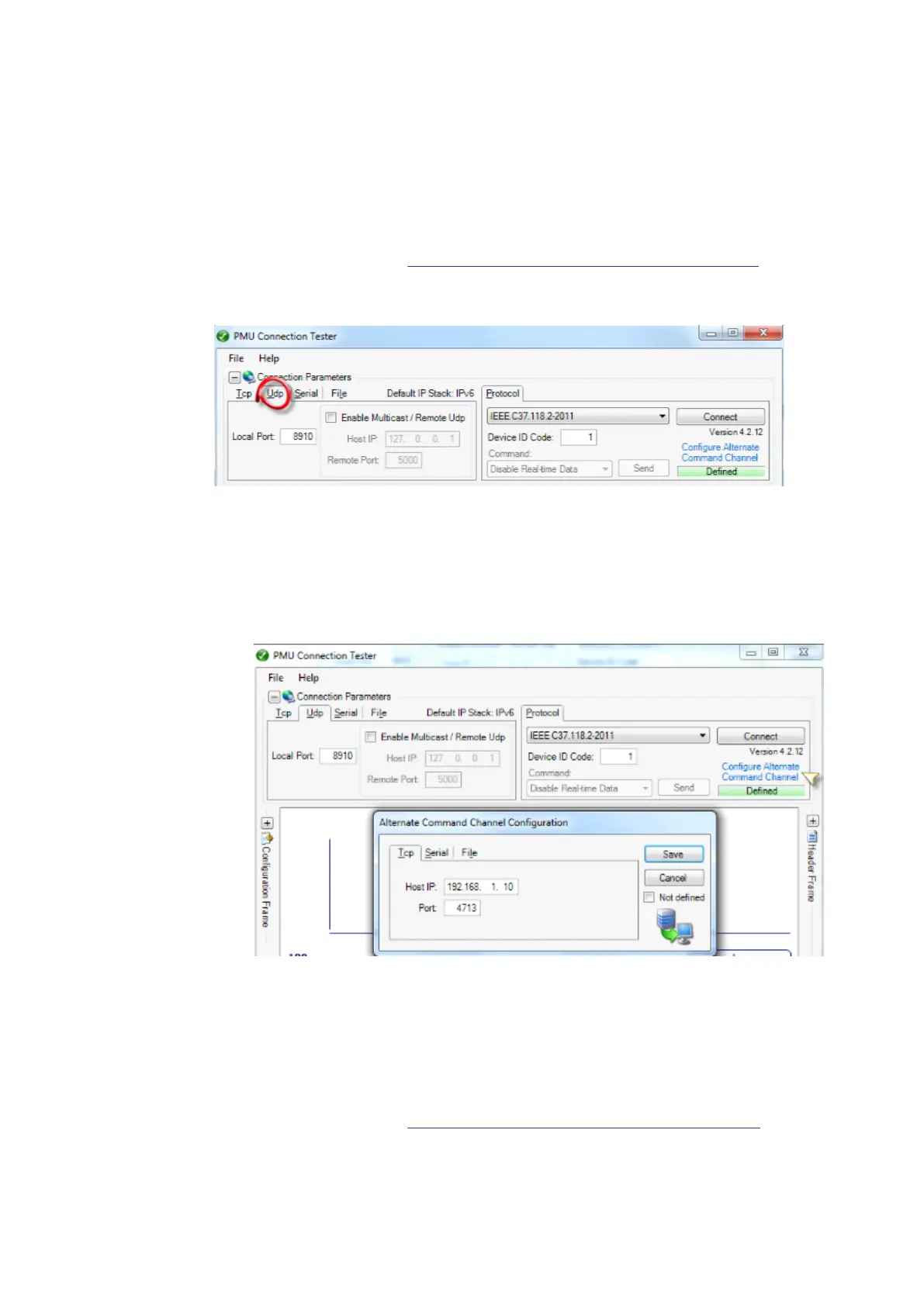
IEC140000136 V1 EN-US
3.1. Set the Local Port to UDP destination port defined in the PMU under the parameter
UDPDestPort1 (Default value: 8910).
3.2. Click the Configure Alternate Command Channel to configure the TCP channel. A new
window will pop up. A TCP channel needs to be configured in order to control the UDP
data communicatiuon and transfer the header, configuration and command frames.
IEC140000137 V1 EN-US
3.3. Set the Host IP as the PMU IP address configured for the port in use. Here the LANAB:1
IPAddress (192.168.1.10) is set.
3.4. Set the Port as the TCP port defined in the PMU for control of data sent over UDP client
group 1 (Default value: 4713). This can be found under the parameter
TCPportUDPdataCtrl1 as one of the UDP communication parameters.
3.5. Save the Alternate Command Channel Configuration settings.
3.6. Continue to the section
Verifying the IEEE C37.118/1344 UDP communication
Section 9 1MRK 505 378-UEN Rev. K
Establishing connection and verifying the IEEE C37.118/1344 communication
70 Line differential protection RED670
Commissioning manual
© 2017 - 2022 Hitachi Energy. All rights reserved



 To Next Page