SJ100 Inverter
Configuring
Drive Parameters
3–33
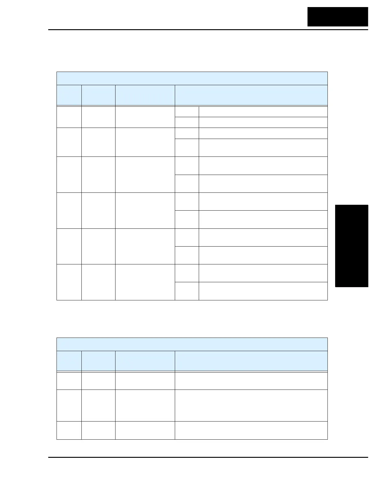
Output Summary Table - this table shows all six functions for the logical outputs (11,
12) at a glance. Detailed descriptions of these functions, related parameters and settings,
and example wiring diagrams are in Chapter 4, starting on page 4–21.
Analog Summary Table - this table shows all three functions for the analog output FM
(frequency meter) terminal at a glance. Detailed descriptions, related parameters and
settings, and example wiring diagrams are in Chapter 4, starting on page 4–27.
Output Function Summary Table
Option
Code
Terminal
Symbol
Function Name Description
00 RUN Run signal ON when inverter is in Run Mode
OFF when inverter is in Stop Mode
01 FA1 Frequency arrival
type 1 signal
ON when output to motor is at the set frequency
OFF when output to motor is off, or in any accelera-
tion or deceleration ramp
02 FA2 Frequency arrival
type 2 signal
ON when output to motor is at or above the set
frequency, even if in accel. or decel. ramps
OFF when output to motor is off, or at a level below
the set frequency
03 OL Overload advance
notice signal
ON when output current is more than the set thresh-
old for the overload signal
OFF when output current is less than the set threshold
for the overload signal
04 OD Output deviation for
PID control
ON when PID error is more than the set threshold for
the deviation signal
OFF when PID error is less than the set threshold for
the deviation signal
05 AL Alarm signal ON when an alarm signal has occurred and has not
been cleared
OFF when no alarm has occurred since the last
clearing of alarm(s)
Analog Function Summary Table
Option
Code
Terminal
Symbol
Function Name Description
00 A-F Analog frequency
monitor
PWM (pulse-width-modulated) voltage output which has
a duty cycle proportional to the inverter output frequency
01 A Analog current
output monitor
PWM (pulse-width-modulated) voltage output which has
a duty cycle proportional to the inverter output current to
the motor. It reaches 100% duty cycle when the output
reaches 200% of the rated inverter current.
02 D Digital frequency
output monitor
FM (frequency-modulated) voltage output with a constant
50% duty cycle. Its frequency = inverter output frequency.

 Loading...


