SJ300 Inverter
Operations
and Monitoring
4–61
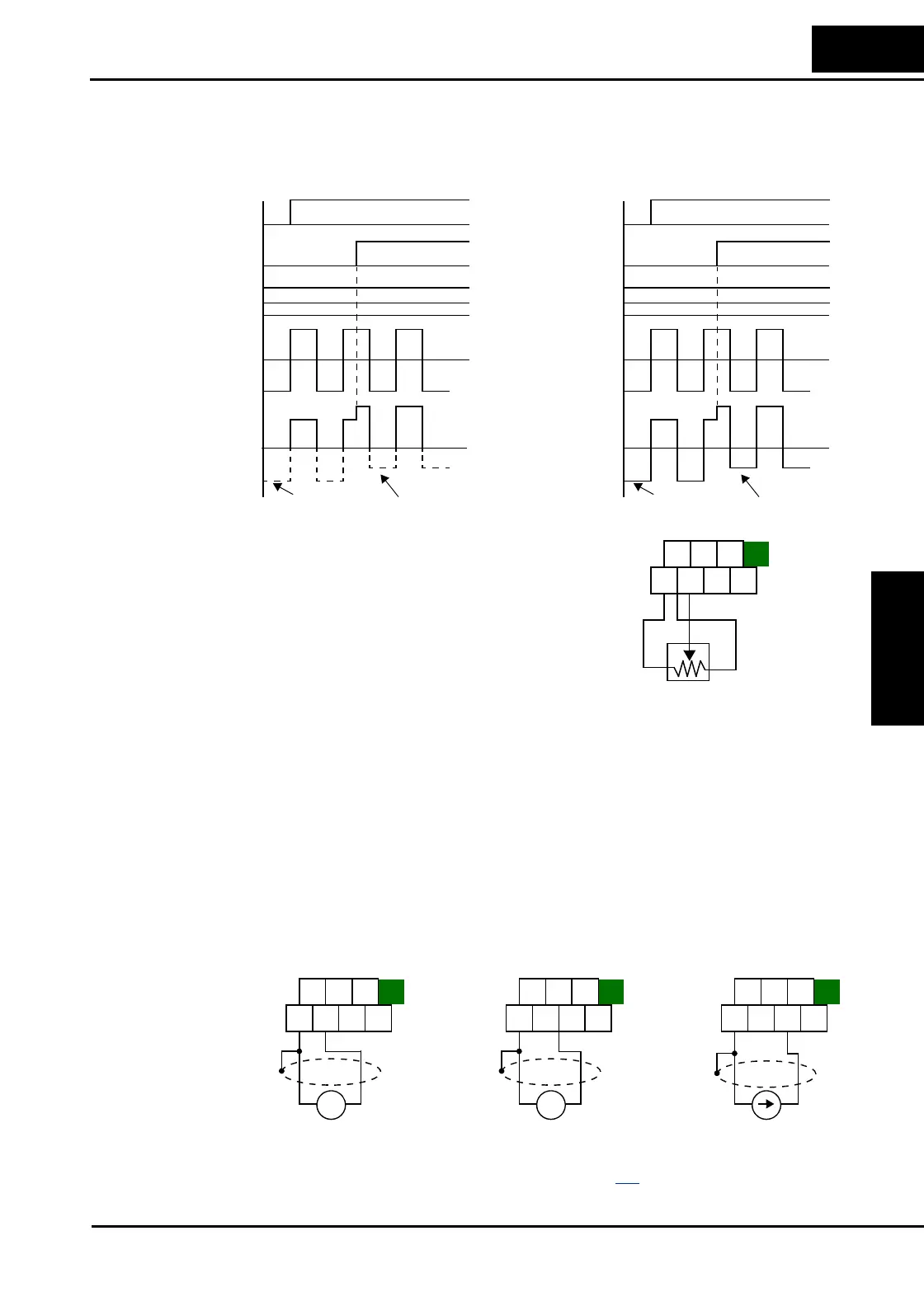
The examples below show how the use of the [AT] input during operation enables/disables the
Trim Frequency Command input [O2]—[L]. The [O2]—[L] input may be used alone, or as an
offset control for the primary analog input.
Wiring Examples Using an external potentiometer is a common way to
control the inverter output frequency (and a good way
to learn how to use the analog inputs). The potentiome-
ter uses the built-in 10V reference [H] and the analog
ground [L] for excitation, and the voltage input [O] for
the signal. By default, the [AT] terminal selects the
voltage input when it is OFF. Take care to use the
proper resistance for the potentiometer, which is
1 to 2kΩ, 2 Watts.
Voltage Input – The 0–10V voltage input circuit uses terminals [L] and [O]. Attach the signal
cable’s shield wire to terminal [L] on the inverter only. DO NOT ground the shield at its other
end. Maintain the voltage within specifications (do not apply negative voltage). Normally a
full-span input level (10V) will give the maximum motor frequency. You can use parameter
A014 to select a lower voltage for full output frequency (such as using a 5V input signal).
Bipolar Voltage Input – The -10 / 0 / +10V voltage input circuit uses terminals [L] and [O2].
Attach the cable’s shield wire to terminal [L] on the inverter only. Maintain the voltage within
specifications. Only apply a negative voltage if this input is configured for bipolar use.
Current Input – The current input circuit uses terminals [OI] and [L]. The current comes from
a sourcing type transmitter; a sinking type will not work! This means the current must flow into
terminal [OI], and terminal [L] is the return back to the transmitter. The input impedance from
[OI] to [L] is 250 Ohms. Attach the cable’s shield wire to terminal [L] on the inverter only.
[FW] terminal
External frequency
command
[O/OI] terminal
[AT] terminal
Actual frequency
command
0
Example 1: Without reverse Example 2: With reverse
Trim frequency
command
[O2] terminal
F
OI
F
OI
+ F
O2
F
O2
0
F
O
0
F
O
+ F
O2
[FW] terminal
External frequency
command
[O/OI] terminal
[AT] terminal
Actual frequency
command
0
Trim frequency
command
[O2] terminal
F
OI
F
OI
+ F
O2
F
O2
0
F
O
0
F
O
+ F
O2
forward
reverse
H O2
FM
AM
O OIL
AMI
1 to 2 kΩ, 2W
L
H
H O2
FM
AM
O OIL
AMI
+ –
0 to 9.6 VDC,
0 to 10V nominal
4 to 19.6 mA DC,
4 to 20 mA nominal
See I/O specs on page 4–9.
+ –
-10 to 9.6 VDC,
0 to 10V nominal
Standard Voltage Input Bipolar Voltage Input Current Input
H O2
FM
AM
O OIL
AMI
H O2
FM
AM
O OIL
AMI

 Loading...


