Chapter 2 Installation and Wiring
2 - 19
2.2.3 Wiring of the control circuit
(1) Wiring instructions
1) Terminals L and CM1 are common to I/O signals and isolated from each other.
Do not connect these common terminals to each other or ground them.
Do not ground these terminals via any external devices. (Check that the external devices connected
to these terminals are not grounded.)
2) Use a shielded, twisted-pair cable (recommended gauge: 0.75 mm
2
) for connection to control circuit
terminals, and connect the cable insulation to the corresponding common terminal. (Tightening
torque:0.7Nm,max torque:0.8Nm)
3) The length of cables connected to control circuit terminals must be 20 m or less. If the cable length
exceeds 20 m unavoidably, use a VX-compatible controller (RCD-A) (remote operation panel) or
insulated signal converter (CVD-E).
4) Separate the control circuit wiring from the main circuit wiring (power line) and relay control circuit
wiring.
If these wirings intersect with each other unavoidably, square them with each other. Otherwise, the
inverter may malfunction.
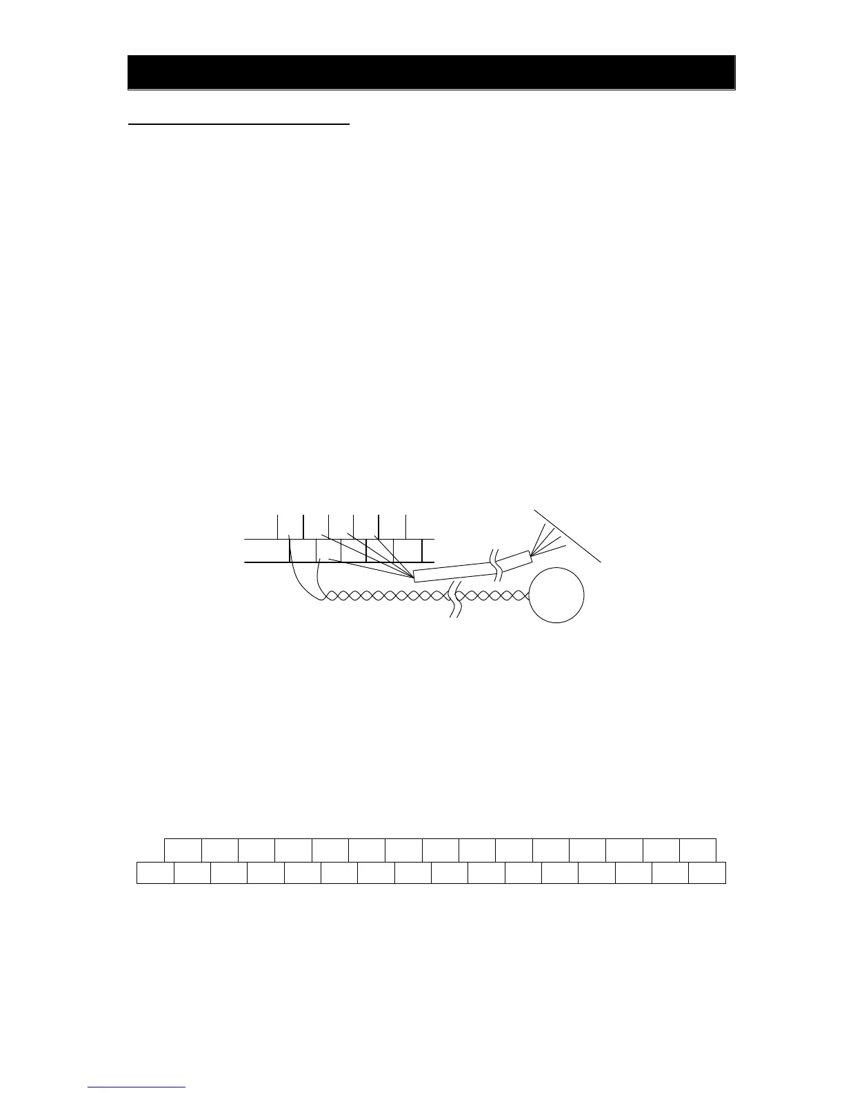
5) Twist the cables connected from a thermistor to the thermistor input terminal (TH) and terminal CM1,
and separate the twisted cables from other cables connected to other common terminals.
Since very low current flows through the cables connected to the thermistor, separate the cables
from those (power line cables) connected to the main circuit. The length of the cables connected to
the thermistor must be 20 m or less.
6) When connecting a contact to a control circuit terminal (e.g., an intelligent input terminal), use a relay
contact (e.g., crossbar twin contact) in which even a very low current or voltage will not trigger any
contact fault.
7) When connecting a relay to an intelligent output terminal, also connect a surge-absorbing diode in
parallel with the relay.
8) Do not connect analog power supply terminals H and L or interface power supply terminals P24 and
CM1 to each other.
Otherwise, the inverter may fail.
(2) Layout of control circuit terminals
H O2 AM FM TH FW 8 CM1 5 3 1 14 13 11 AL1
L O OI AMI P24 PLC CM1 7 6 4 2 15 CM2 12 AL0 AL2
Terminal screw size: M3(Tightening torque:0.7Nm,max torque:0.8Nm)
(3) Switching the input control logic
- In the factory setting, the input control logic for terminal FW and intelligent input terminals is the sink
logic.
To switch the input control logic to the source logic, remove the jumper connecting terminals P24 and
PLC on the control circuit block, and then connect terminals PLC and CM1 with the jumper.
TH
PL
CM1 7 6
CM1 8 FW
Thermistor
PLC
5
4

 Loading...


