26
PMEN0645 rev.0 - 04/2023
5
WATER PIPING
REFRIGERANT PIPING
6 Remove as much air from inside the water circuit as possible through the indoor air purger and
other air vents in the installaon (fan coils, radiators...).
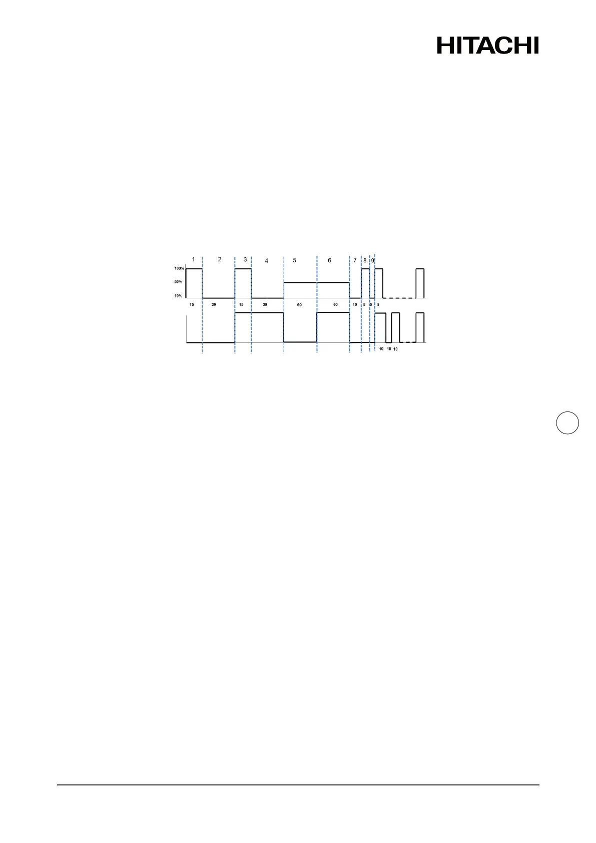
7 Start the air purge procedure test. There are two modes (Manual or Automac) which helps in
case of installaons with heang and DHW operaon:
a. Manual: Start and stop the unit manually using the unit controller (Run/Stop buon) and
also using the DSW4 pin 2 of the PCB1 (ON: Forced to derive to DHW coil; OFF: Forced to
derive to space heang).
b. Automac: Select the air purge funcon using the user controller. When the automac
air purge funcon is running, the pump speed and the posion of the 3-way valve (space
heang or DHW) are automacally changed.
Water
pump
DHW
3Wv
Seconds
Seconds
Repeat...
Repeat...
ON
OFF
8 If a lile quanty of air is sll remaining in the water circuit, it will be removed by the automac
air purger of the indoor unit during the rst hours of operaon. Once the air in the installaon
has been removed, a reducon of water pressure in the circuit is very likely to occur. Therefore,
addional water should be lled unl water pressure returns to an approximate level of 1.8 bar.
NOTE
• The indoor unit is equipped with an automac air purger (factory supplied) at the highest
locaon of the indoor unit. Anyway, if there are higher points in the water installaon, air might
be trapped inside water pipes, which could cause system malfuncon. In that case, addional air
purgers (eld supplied) should be installed to ensure no air enters into the water circuit. The air
vents should be located at points which are easily accessible for servicing.
• The water pressure indicated on the indoor unit manometer may vary depending on the water
temperature (the higher temperature, the higher pressure). Nevertheless, it must remain above
1 bar in order to prevent air from entering the circuit.
• Fill in the circuit with tap water. The water in the heang installaon must comply with EN
direcve 98/83 EC. Non-sanitary controlled water is not recommended (for example, water from
wells, rivers, lakes, etc.)
• The maximum water pressure is 3 bar (nominal opening pressure of the safety valve). Provide
adequate reducon pressure device in the water circuit to ensure that the maximum pressure is
NOT exceeded.
• For heang oor system, air should be purged by means of an external pump and an open circuit
to prevent the formaon of air pockets.
• Check carefully for leaks in the water circuit, connecons and circuit elements.
 Loading...