35
PMEN0645 rev.0 - 04/2023
6
ELECTRICAL CONNECTION
ELECTRICAL AND CONTROL SETTINGS
• Check to ensure that exisng installaon (main power switches, circuit breakers, wires,
connectors and wire terminals) already complies with the naonal and local regulaons.
• The use of the DHW tank heater is disabled as factory seng. If it is desired to enable the
DHW tank heater operaon during normal indoor unit operaon, adjust the DSW4 pin 3 of the
PCB1 to the ON posion and use the adequate protecons. Refer to the secon “6.2 Electrical
connecon” for the detailed informaon.
6.2 Electrical connecon
! CAUTION
• Check to ensure that the eld supplied electrical components (mains power switches, circuit
breakers, wires, connectors and wire terminals) have been properly selected according to the
electrical data indicated on this chapter and they comply with naonal and local codes. If it is
necessary, contact with your local authority in regards to standards, rules, regulaons, etc.
• Use a dedicated power circuit for the indoor unit. Do not use a power circuit shared with the
outdoor unit or any other appliance.
6.2.1 Wiring size
Use wires which are not lighter than the polychloroprene sheathed exible cord (code designaon
60245 IEC 57).
◆ Split system - Indoor unit
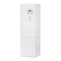
YUTAKI S Combi
Model Power supply Operaon mode
Maximum
current
(A)
Power supply cables
Transming
cables
Actuator
cables
EN 60335‑1 EN 60335‑1
RWD‑(1.5‑3.0)RW2E‑220S(‑K)
~ 230V 50Hz
Without electric heaters 0.6 2 x 0.75 mm
2
+ GND
2 x 0.75 mm
2
(Shielded
cable)
2 x 0.75 mm
2
+ GND
With electric heater 13.7 2 x 2.5 mm
2
+ GND
With DHW tank heater 12.6 2 x 2.5 mm
2
+ GND
With electric and DHW
tank heaters
25.6 2 x 6.0 mm
2
+ GND
3N~400V 50Hz
Without electric heaters 0.6 4 x 0.75 mm
2
+ GND
With electric heater 9.3 4 x 2.5 mm
2
+ GND
With DHW tank heater
12.6
4 x 2.5 mm
2
+ GND
With electric and DHW
tank heaters
12.6 4 x 2.5 mm
2
+ GND
 Loading...
