45
PMEN0645 rev.0 - 04/2023
6
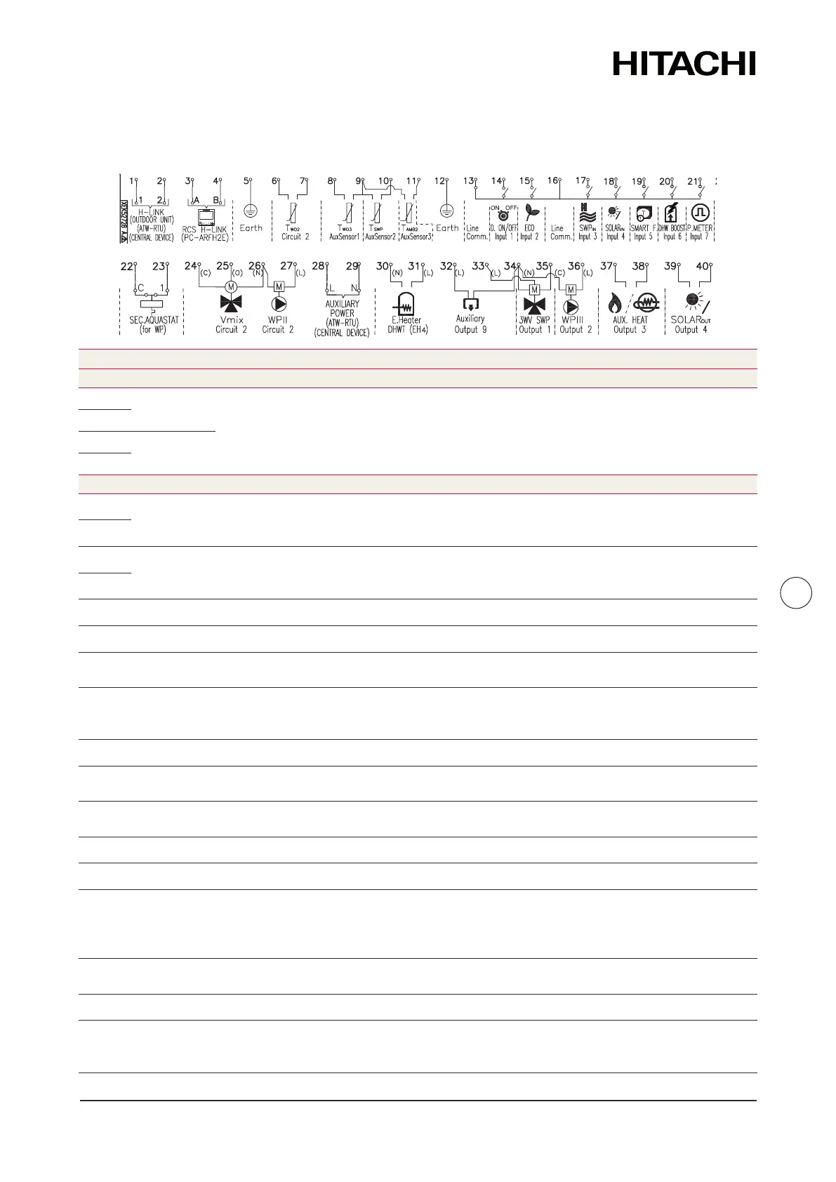
TERMINALBOARDCONNECTIONS
ELECTRICAL AND CONTROL SETTINGS
6.4.2.2 Summary of terminal board connecons
N
~ 230V 50Hz
3N~ 400V 50Hz Main power supply connecon
L1
L2
‑
L3
1
H‑LINK commutaon
The H‑LINK transmission has to be done between the indoor unit and
the terminals 1‑2 of either outdoor unit, ATW‑RTU or any other central
2
3
H‑LINK communicaon for
remote control switch
Terminals for the connecon of the YUTAKI unit controller.
4
5 Earth Earth connecon for the 3 way valve and water pump
6 Common thermistor Common terminal for thermistor.
7
Thermistor for water outlet
temperature of second cycle
The sensor is used for the second temperature control and should be
posioned aer the mixing valve and the circulaon pump.
8
Thermistor for water outlet
temperature aer hydraulic
Water sensor for hydraulic separator, buer tank or boiler combinaon.
9 Common thermistor Common terminal for thermistors.
10
Thermistor for swimming pool
water temperature
The sensor is used for the swimming pool temperature control and should
be posioned inside plate heat exchanger of the swimming pool.
11
Thermistor for second ambient
temperature
The sensor is used for the second ambient temperature control and it
should be posioned outdoors.
12 Earth Earth connecon for the 3 way valve and water pump
13 Common line Terminal Line common for input 1 and input 2.
14
Input 1 (Demand ON/OFF) (*)
The air to water heat pump system has been designed to allow the
connecon of a remote thermostat to eecvely control your home’s
temperature. Depending on the room temperature, the thermostat will
turn the split air to water heat pump system ON and OFF.
15 Input 2 (ECO mode) (*)
Available signal which allows to reduce the water seng temperature of
circuit 1, circuit 2 or both.
16 Common line Terminal Line common for inputs 3, 4, 5, 6, 7.
17 Input 3 (Swimming pool) (*)
Only for swimming pool installaons: It is necessary to connect an
external input to the air to water heat pump to provide signal when the
water pump of swimming pool is ON.
 Loading...