59
PMEN0645 rev.0 - 04/2023
7
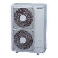
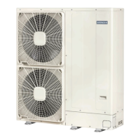
REMOVING THE COVERS
MAINTENANCE
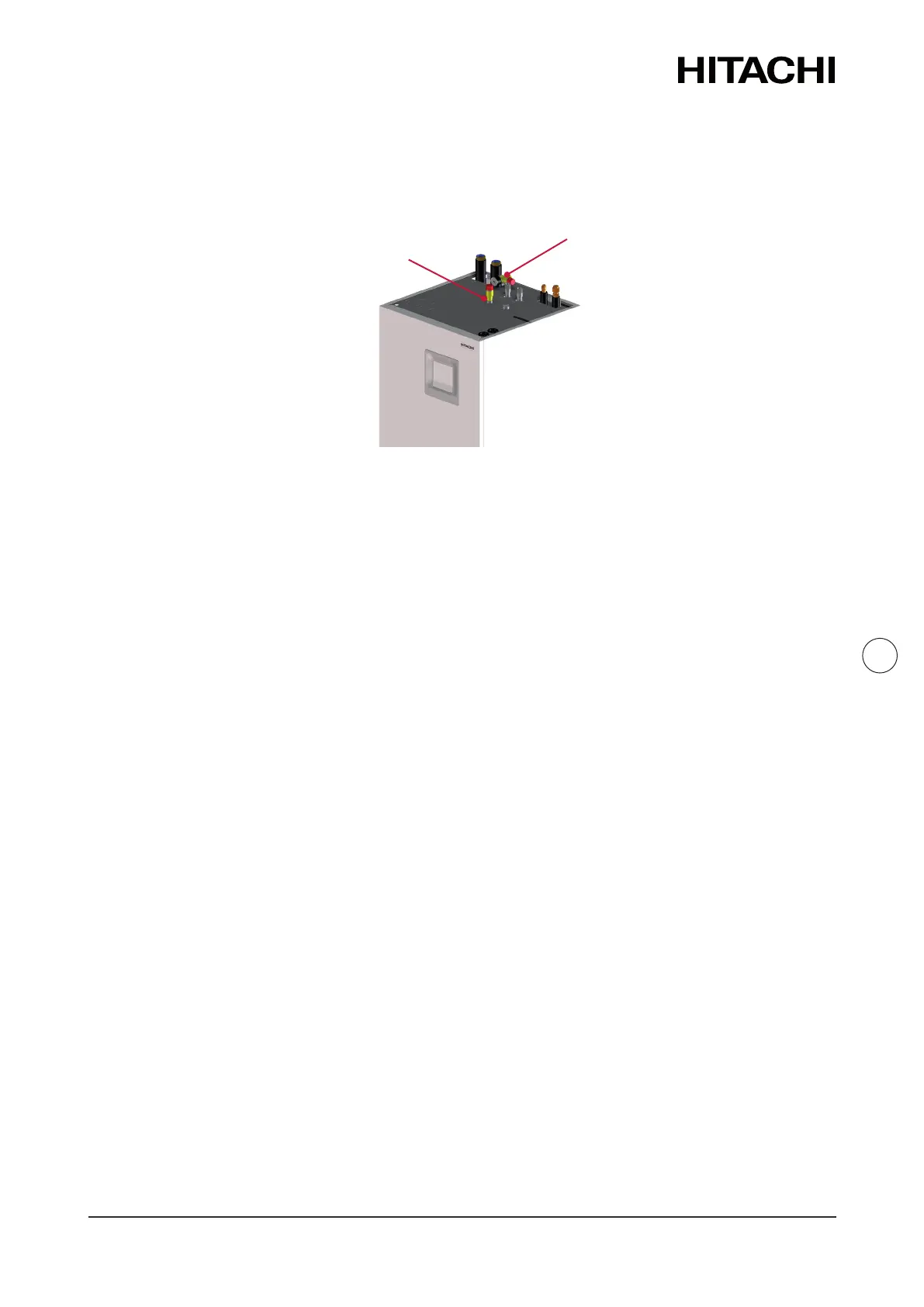
7.1.0.5 Drain pipes connecon
For a correct drainage, connect the drain pipe for the safety valve (located at the top rear side of
the unit) to the general draining system.
Safety valve
P&T relief valve
(Only for UK market)
NOTE
• The safety valve is acvated when water pressure reaches 3 bars.
• Drain taps must be provided at all low points of the installaon to permit complete drainage of
the circuit during servicing.
• P&T relief valve is acvated when water pressure reaches 7 bar and/or water temperature
reaches 96°C
• Discharge pipe must be made of metal or any other material capable to withstand the high
pressure and high temperature from the P&T relief valve.
• For a correct installaon and workpipe of the discharge pipe on UK market models, refer to UK
Building Requirements
7.1.1 Test and check
Finally, test and check the following items:
• Water leakage
• Refrigerant leakage
• Electrical connecon
• ...
NOTE
Please refer to the chapters of “5.2.3 Refrigerant charge”, “5.3.2.1 Water lling” and
“Commissioning” in this document and refer the Outdoor unit Installaon and Operaon manual
for the specic details about refrigerant charge tasks.
! DANGER
Do not connect the power supply to the indoor unit prior to lling the space heang circuit (and
DHW circuit if it were the case) with water and checking water pressure and the total absence of
any water leakage.
 Loading...