E1 Series Servo Drive EtherCAT(CoE) Communications Command Manual Object Dictionary
3-18 HIWIN MIKROSYSTEM Corp.
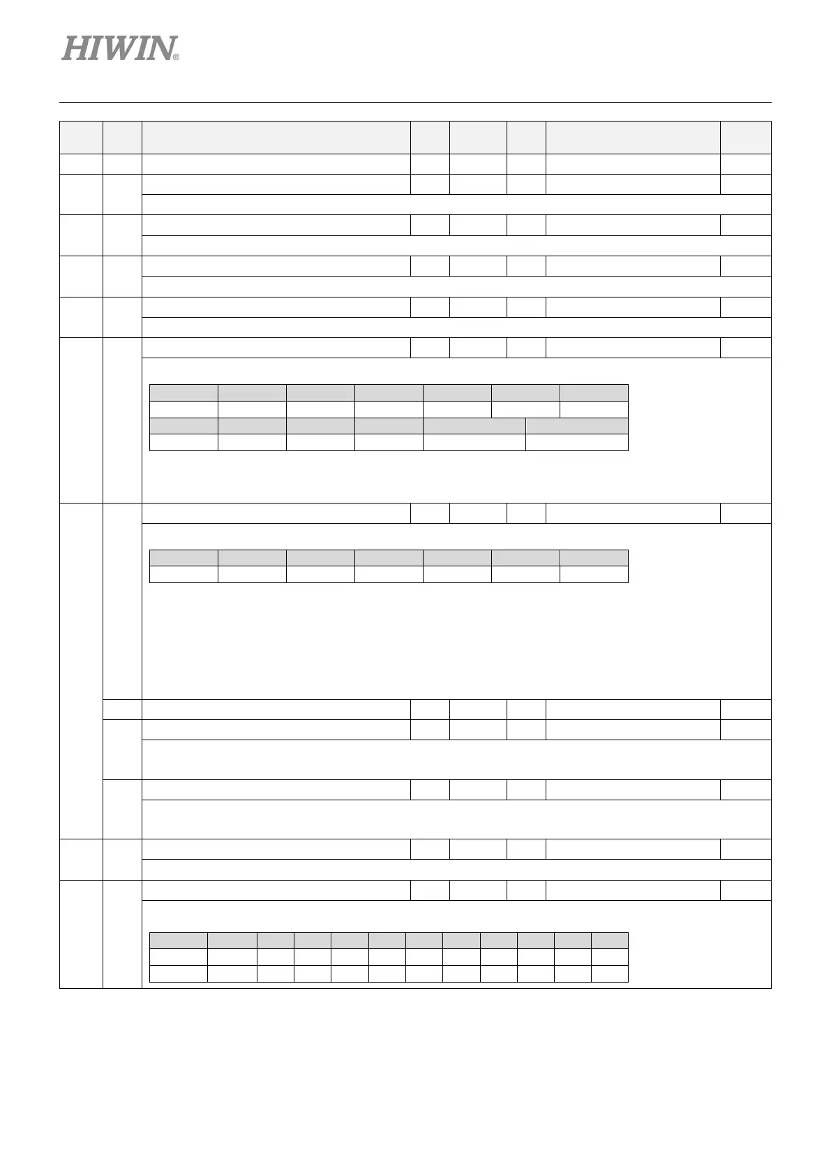
Index
Sub-
Index
Name
Data
type
Access PDO Valid value Unit
60C6h 00h Max deceleration U32 rw Y 0 ~ 4294967295 inc/s
2
60E0h 00h
Positive torque limit value U16 rw Y 0 ~ 65535 0.1%
The configured maximum positive torque in the motor.
60E1h 00h
Negative torque limit value U16 rw Y 0 ~ 65535 0.1%
The configured maximum negative torque in the motor.
60F4h 00h
Following error actual value I32 ro Y -2147483648 ~ 2147483647 inc
60F4h (following error actual value) = 6062h (position demand value) – 6064h (position actual value)
60FCh 00h
Position demand internal value I32 ro Y -2147483648 ~ 2147483647 count
Internal command position
60FDh 00h
Digital inputs U32 ro Y 0 ~ FFFFFFFFh -
The input status of external input signal. The definition of each bit is as below.
31 ... 24 23 22 21 20 19 18
The value of each bit is defined as follows.
0: switched off
60FEh
-
Digital outputs - - - - -
They are used to control the external output signal.
Reserved O5 O4 O3 O2 O1 Reserved
This object controls the status of the general-purpose output signals from CN6 on E1-series drive.
Subindex 1 is used to control the status of the output signals. Subindex 2 determines which output signals in subindex 1 are
enabled.
If drive status outputs are assigned to O1~O5 signals in object 3514h, 3515h and 3516h, the status of this object will be output
in the logic of ORs. If any of these signals is assigned to functions that are enabled with object 3514h, 3515h, or 3516h, use
Bit Masks in subindex 2 to disable the corresponding signal. By doing so, the signal will not be duplicated.
Brake can only be controlled by this object when servo is not on.
00h Number of entries U8 ro - 2 -
01h
Physical outputs U32 rw Y 0 ~ FFFFFFFFh -
Control the output of the external signal. The value of each bit is defined as follows.
0: switched off
02h
Bit mask U32 rw Y 0 ~ FFFFFFFFh -
The output signal mask. The value of each bit is defined as follows.
0: disable output
60FFh 00h
Target velocity I32 rw Y -2147483648 ~ 2147483647 inc/s
Velocity command. The value is limited by 607Fh (max profile velocity).
6502h 00h
Supported drive modes U32 ro - 0 ~ FFFFFFFFh -
The object indicates the operation modes supported by the drive. When the bit value is 1, the operation mode is supported.
Bit 31...10 9 8 7 6 5 4 3 2 1 0
Op mode - cst csv csp ip hm - tq pv vl pp

 Loading...


