HQ Series Quarter-turn Electric Actuator
Installation Operation& Maintenance Manual
Doc No. : HumG-HQ-21 Rev2 Page 10 / 26 Valve Automation Leader, HKC
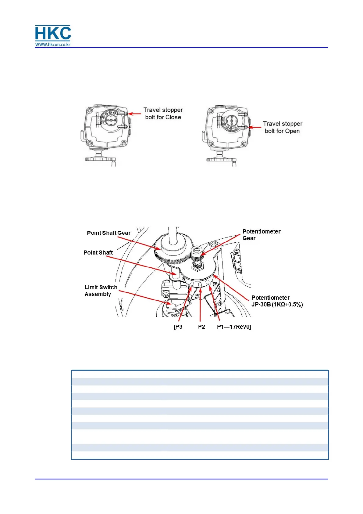
4.6.1. Loosen both (open and close) travel stopper bolt nuts by 3-4 threads.
4.6.2. By turning the hand wheel, manually operate the actuator so that it is in close position until it
makes a contact with the closed limit switch.
4.6.3. Tighten the close travel stopper bolt until it contacts the 2
nd
worm wheel (in this position the close
travel stopper bolt should not be able to travel any further).
4.6.4. Loosen back the close travel stopper bolt by on turn and tighten the close travel stopper bolt nut.
4.6.5. Repeat the same operation for setting of the open travel stopper bolt.
4.7. Setting Potentiometer (Replacement and Setting)
The potentiometer has been calibrated at factory. However, if re-calibration is required, proceed as
follows:
4.7.1. Manually rotate the hand wheel of the actuator to fully closed position.
4.7.2. [While measuring the resistance between P1 and P2, gently rotate the Potentiometer Gear until it
reaches between 80 - 120 Ω (100 Ω preferred).--- 16Rev1]
4.7.3. Engage the Potentiometer Gear into the Point Shaft Gear and use an L-wrench to tighten the
screw.[Delete “Danger” --- 16 Rev1]
4.8. Current Position Transmitter – CPT (Optional)
The potentiometer is used for the actuator signal feedback. It reads a resistance value corresponds to the
current position of the actuator and transfers to CPT card. The CPT indicates the current position of the
actuator throughout the stroke by a 4 ~ 20mA output signal.
4.8.1. Standard Features
Position Conversion Accuracy
Dielectric Strength
(from Input power to ground) ------ 15 Rev0]

 Loading...