UK. SERVICE TRAINING CENTRE
Warning this information is for HOBART STILL trained personnel only.
Reproduction of this information is prohibited without the written consent of HOBART STILL.
Page: 5
02/95
1712
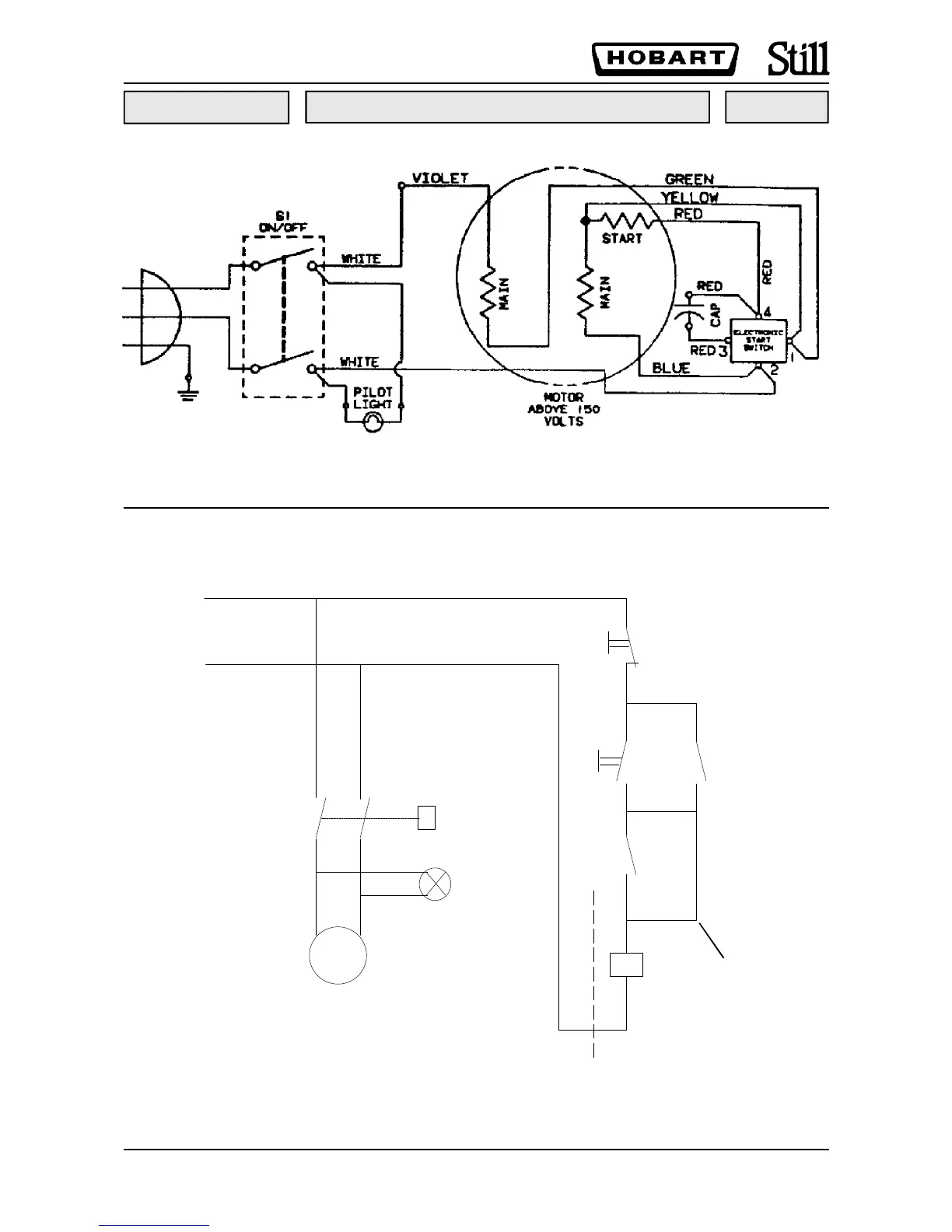
WIRING DIAGRAM
L
N
K1
K1
Indicator
lamp
MOTOR
Start
Stop
blade
guard
switch
K1
Link wire
(see below)
This circuit is the modification carried out to fit NVR system to UK requirements, therefore use this diagram
for the control circuit.
The blade guard switch is not fitted on
later machines that have a blade guard
protection ring and is therefore linked
out
Note:- K1 is fitted inside a box underneath the machine
white
white
 Loading...