OM-2244 / Operation and Maintenance Manual
DCS-600 / Series 500082 / Solid State Transformer-Rectifiers
Improper connections will cause damage. Contact factory if your equipment
specification information and/or voltage changeover diagram does not agree with your
rated three-phase input voltage.
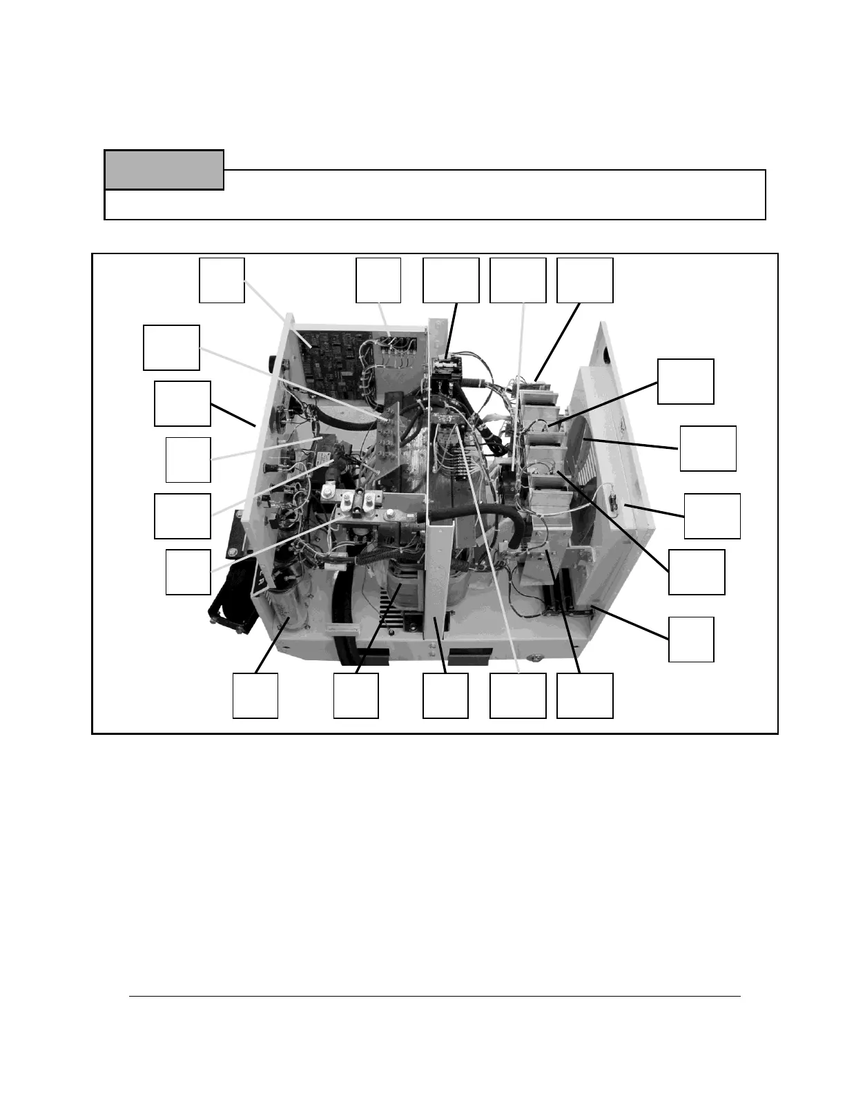
1. Power Transformer (T1)
2. Capacitors (C15, C16, C17)
3. 28.5 VDC Output Contactor (K2)
4. Pre-load Resistor Assembly (R2, R3, R4)
5. Choke (L1)
6. Control Transformer (T2)
7. Interior Panel
8. Fuse Block (F2 through F7)
9. Printed Circuit Board (A1)
10. Line Contactor (K1)
11. Front Panel
12. Voltage Changeover Board
13. SCR Heat Sink Assembly
14. Fan Blade
15. Fan Motor (B1)
16. Feedback Shunt (R12)
17. Fan Turn-on Thermostat (S4)
18. Overload Thermostat (S5)
19. Fan Fuse (F1)
20. Ammeter Shunt (R11)
Figure 5 Internal Components of GPU-600
 Loading...