OM-2244 / Operation and Maintenance Manual
DCS-600/ Series 500082 / Solid State Transformer-Rectifiers
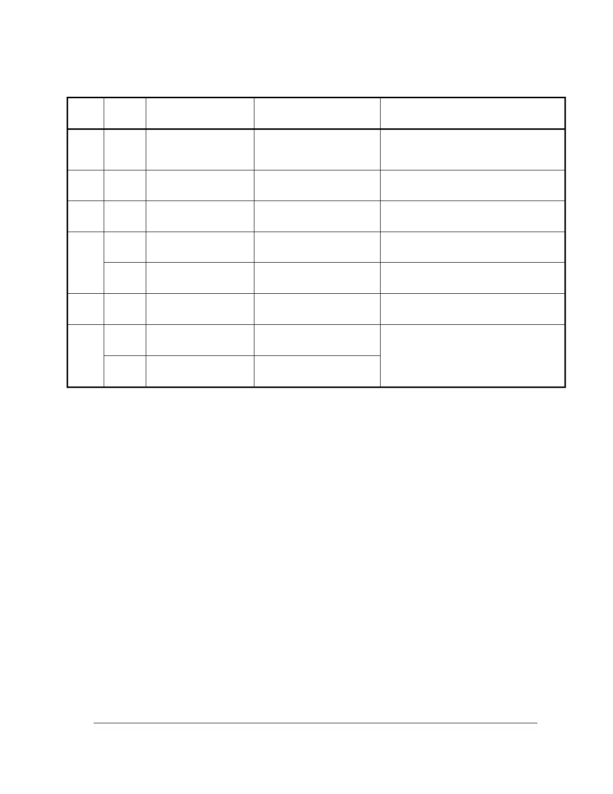
Checks for null (0) by R38 for the no
load current signal
Checks voltage slope calibrated with
R102
Checks reference voltage adjusted by
R101
Checks output volts set by R109 in 28
VDC mode
Checks output volts set by R110 in 14
VDC mode
Checks R60 overload current setting
Optional test
Checks overload light, DS2, and circuit
functioning (Q10)
Table 2 GPU Circuit Board Tests
4) Circuit Board Calibration
Equipment Requirements
Calibration requires the following equipment:
a load bank – able to pull 2200 amps at 28.5 volts
two voltmeters - ± 2% accuracy
an oscilloscope
a 3.3 k resistor
small test clips
Also, if your GPU is set up for bridge interlock and remote connection option, you will need to add
switches:
Connect normally open "Start" switch between TB101-1 and TB101-2.
Connect normally closed "Stop" switch between TB101-2 and TB101-3.
 Loading...