OM-2244 / Operation and Maintenance Manual
DCS-600/ Series 500082 / Solid State Transformer-Rectifiers
f) Loosen the cable clamp at the base and remove the output cable from the GPU.
g) If the unit is a bridge mount unit, also disconnect and remove the remote control cables.
h) If the unit is bridge mount or fixed mount, attach a lifting hoist or forklift to the bottom of the GPU and
remove the mounting screws or bolts that attach the GPU to its mounting.
i) Carefully remove the GPU.
j) Move the GPU to a clear working area where it can be placed on a solid supporting structure.
k) Re-install the GPU in the reverse order of removal. See Section 1-2 for additional information on
installing the GPU.
4) Component Removal and Replacement
Most of the components in the GPU are easily replaced when necessary. Chapter 1 and Chapter 4 show
the locations of the components in the GPU.
To avoid the danger of electric shock, always make sure that the input power is turned
off at the source and cannot be inadvertently turned back on before working inside the
GPU.
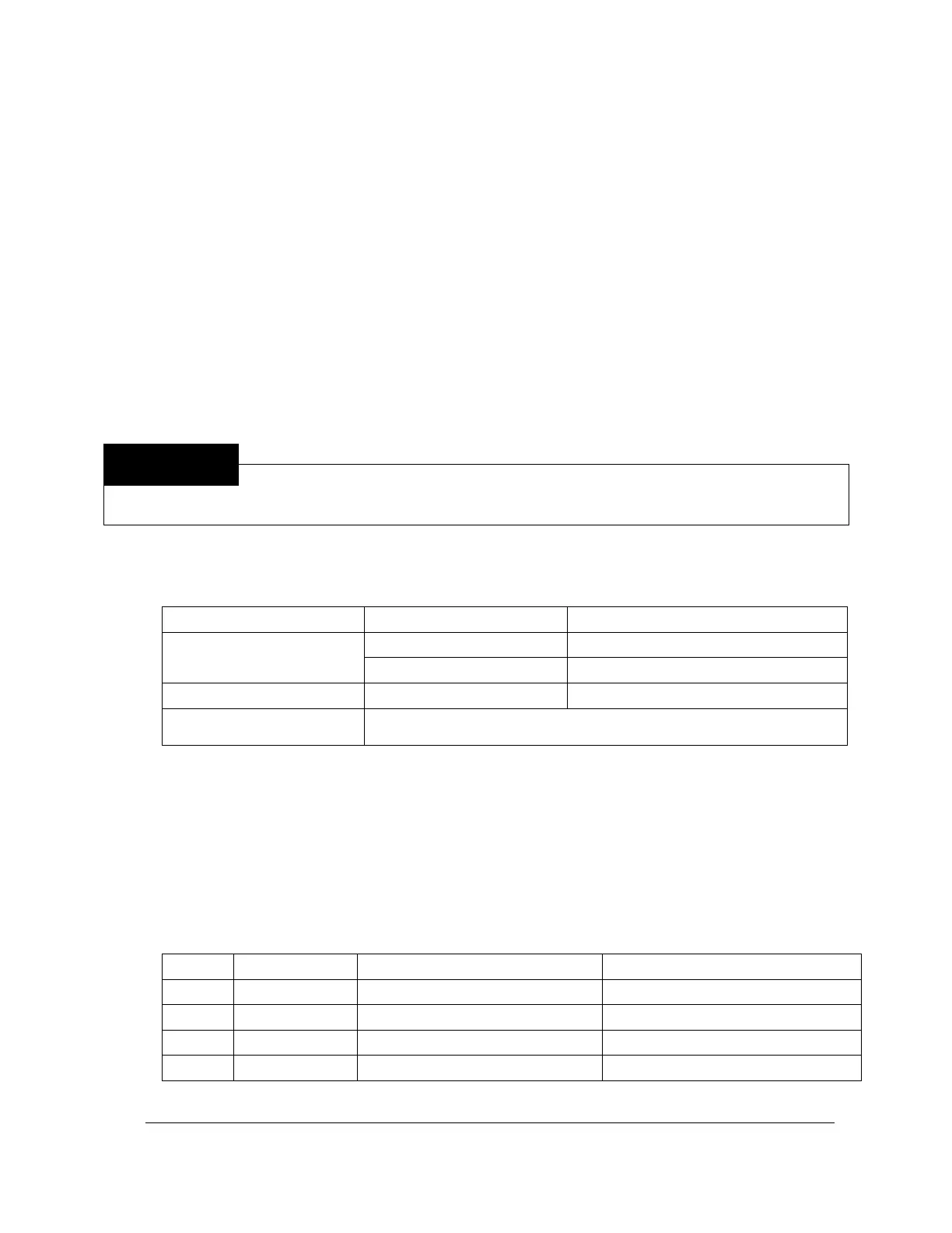
a) Lights
The light bulbs are accessible from the front by unscrewing the lens.
Type 120 MB (120 V, .025 A, T-2-1/2)
No bulb – this is an LED assembly
b) Circuit Board
Chapter 4-3, Figure 2 gives the location and part number of the circuit board. To replace the circuit
board, unplug the connectors and remove the six screws.
c) Fuses
The following table provides the locations and functions of the fuses. If a fuse has blown, check the
related circuitry. Always replace the fuses with similar fuses having the same type and rating.
Fuse block next to circuit board
1 A, 250 V, Type AGC, Fast blow
0.5 A, 250 V, Type AGC, Fast blow
d) Thermostat Switches
 Loading...