OM-2244 / Operation and Maintenance Manual
DCS-600/ Series 500082 / Solid State Transformer-Rectifiers
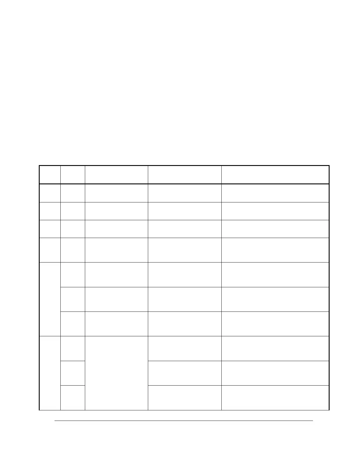
3) Test Procedure
Follow the table steps in this section to verify that the PC board is functioning properly. If the voltage
readings to the PC board common are not within specification, attempt to correct the reading by adjusting
the applicable control. Be certain the operating conditions are exactly as stated in the table.
If the board does not adjust, check the leads, fuses (F2-F7), and connectors. If no external problems are
found, the PC control board is faulty. Replace it with a known good board.
After replacing the board, recheck the voltages. In some cases, minor adjustments may be required for
optimum calibration. If the replacement board shows the same magnitude of error and lack of adjustment
control, it is possible that the control board is not at fault. The voltages in the following table are all
referenced to pc board common, which is Test Point 3 (TP3) and Test Point 15 (TP15). Connect the
negative voltmeter lead to either of those test points.
Checks (+) voltage regulator output set
by U4.
Checks (-) voltage regulator output set
by U5.
Checks unregulated control voltage
needed for 1 and 2
Checks gate pulse timer volts supply
set by CR9
Checks gate pulse timer operation
before phase balancing and
amplification
Checks gate pulse timer operation
before phase balancing and
amplification
Checks gate pulse timer operation
before phase balancing and
amplification
With a 100 A load,
adjust R9 and R10
carefully for lowest
ripple voltage
(typically 100 to 160
mV).
-8.2 VDC ± 10%
(measured with no load)
Checks gate pulse timer operation and
balance adjustment
-8.2 VDC ± 10%
(measured with no load)
Checks gate pulse timer operation and
balance adjustment
-8.2 VDC ± 10%
(measured with no load)
Checks gate pulse timer operation and
balance adjustment.
 Loading...