EasyManuals Logo

Hobart GPU-600 Series User Manual

Hobart GPU-600 Series
116 pages
To Next Page IconTo Next Page
To Previous Page IconTo Previous Page
Page #46 background imageLoading...
Page #46 background image
OM-2244 / Operation and Maintenance Manual
DCS-600/ Series 500082 / Solid State Transformer-Rectifiers
December 15, 2014
Chapter 2-2
Page 4
Test Point
Function
Signal Controlled by:
TP1
SCR Gate Pulse Phase 3
R10
TP2
SCR Gate Pulse Phase 2
R9
TP3
PC Board Common
TP4
+10.0 VDC Timer Voltage
TP5
+15 V Regulated Voltage
TP6
15 V Regulated Voltage
TP7
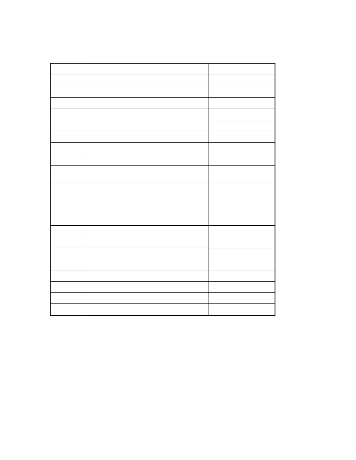
+24 V Unregulated Voltage
TP8
SCR Gate Pulse Phase 1
TP13
Actual Output Voltage (28.5 or 14.25)
R109 (-28.5 V) or
R110 (-14 V)
TP14
Null at zero output current: provides amplified
load amp reading for comparison with
overload limit (TP20) and starting amperage
limit (TP21) set by R13 control on front panel.
R38
TP15
PC Board Common
TP17
Voltage Slope Test Point
R102
TP19
Reference Volt Test Point
R101
TP20
Overload Limit
R60
TP21
Starting Current
R13 (front panel)
TPD
SCR Gate Timer Output Phase 3
TPE
SCR Gate Timer Output Phase 2
TPF
SCR Gate Timer Output Phase 1
TPL
Overload Trip Summing Point
Table 1 GPU Circuit Board Test Points and Controls

Questions and Answers:

Question and Answer IconNeed help?

Do you have a question about the Hobart GPU-600 Series and is the answer not in the manual?

Hobart GPU-600 Series Specifications

General IconGeneral
BrandHobart
ModelGPU-600 Series
CategoryTransformer
LanguageEnglish

Related product manuals