OM-2244 / Operation and Maintenance Manual
DCS-600/ Series 500082/ Solid State Transformer-Rectifiers
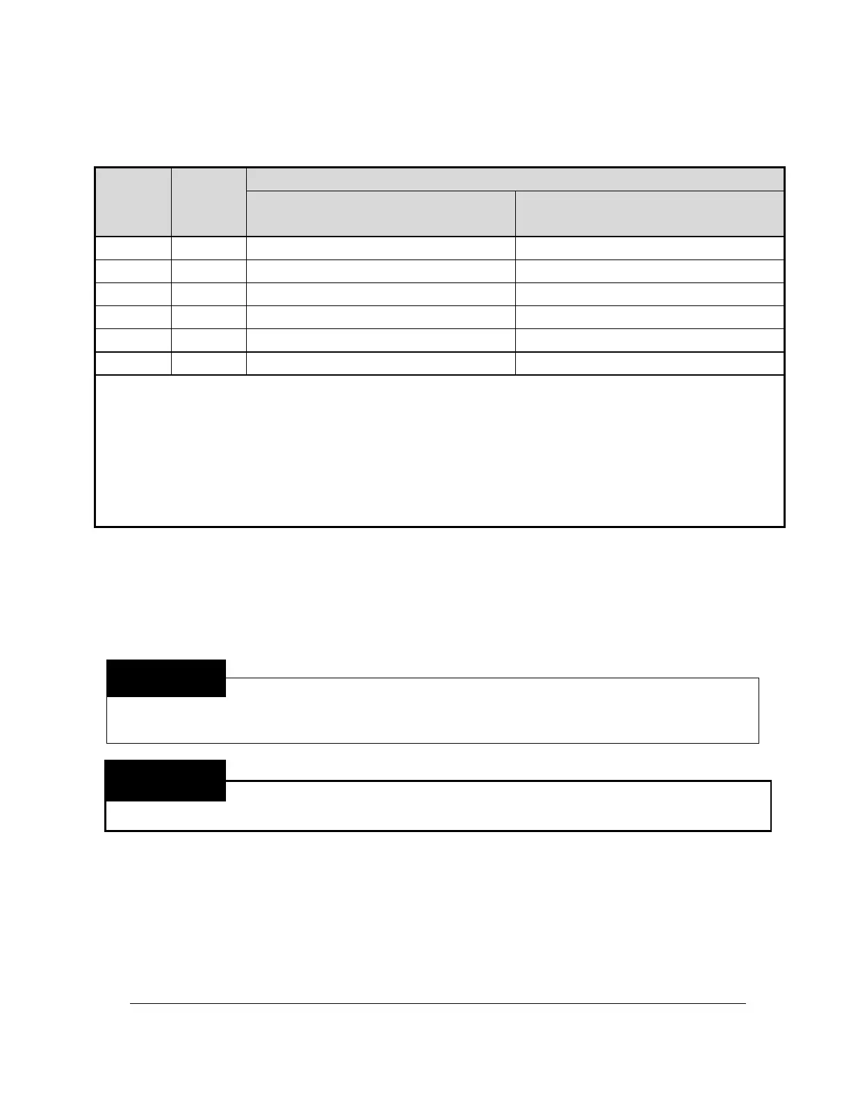
* Conductor sizes listed are for 30 feet or less of each conductor in conduit and for copper conductors having
90º C insulation, such as type FEB, FEPB, RHH, and THHN as based on an ambient temperature of 50° C.
For conductors having other insulation, or for conductors longer than 30 feet, consult local electrical code for
the required conductor size.
** Conductor sizes listed are for 30 feet or less of each conductor in conduit and for copper conductors having
90º C insulation, such as type W, SC, SCE, SCT, PPE, G, and G-GC as based on an ambient temperature of
50° C. For conductors having other insulation, or for conductors longer than 30 feet, consult local electrical
code for the required conductor size.
Figure 1 Recommended Wire and Fuse Size Table
5) Installation
A ITW GSE GPU requires no additional preparation in order to supply power to an aircraft. It needs only
to have its input cable connected to an appropriate source of power and its output cable connected to an
aircraft. Proceed as follows for putting the GPU unit into service.
The method of installation, conductor size, and over-current protection shall conform
to the requirements of the local electrical code, the national electrical code, or other
national codes, as applicable. Qualified persons shall do all installation wiring and
machine reconnection.
Electric shock can kill! Open the disconnect switch, or breaker, and determine that no
voltage is present before removing top canopy and connecting wires between the
input service and power supply or working on the power supply.
a) Locate the Cable Entry Locations
Input and output cable entrance shall be made through the cable entrance holes provided in the GPU
cabinet.
The GPU has an 1.75” diameter entry hole for the input cable on the rear of the unit. The customer is
responsible for supplying a suitable cable clamp.
The GPU canopy has slots on the side for the output cable. A cable clamp holds the output cable to
the unit base.
Please contact the Service Department if you have any problem with this
 Loading...