Fan Installation
**Build Note** The performance of this model lies in attention to detail when
installing the ducting. The templates below are rough estimates and may need
slight adjustments to fit your exact model since each one is slightly different.
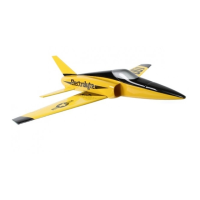
1) Using the templates above as guides, cut front and rear ducting pieces from the included
clear plastic sheet. Each template above has excess material shown (beyond the dashed line)
that helps to make taping the ducting together easier. Suggest 10mm for forward duct, and
8mm each side of rear duct.
Forward Duct Rear Duct
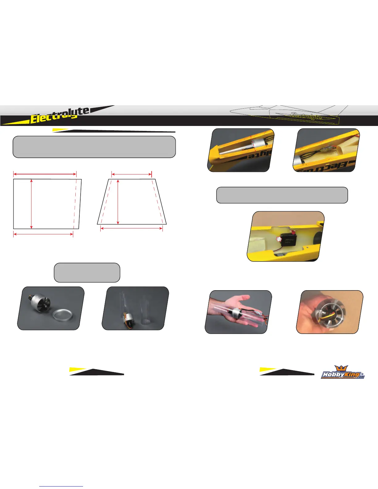
2) Remove front lip piece from fan. This
will not be used for the Electrolyte.
*Thrust Tube Exit Diameter*
- 30mm Yields optimal speed
- 33~34mm Yields better static thrust
3) Using clear tape, tape together the ducting pieces.
For tightest fit of rear ducting, roll it tightly around fan
prior to taping. Make front and rear duct pieces.
4) Test fit fan and ducting into fuselage. Back edge of fan shround will align to 3rd set of screw
holes. (From back) ESC will mount on right side of fuselage, opposite the elevator servo.
6) Using clear tape, carefully attach ducting to fan to make complete unit. Check your motor
for proper rotation direction prior to installation. Route motor wires as shown, minimizing
force on the wires to prevent long term damage.
5) Mount elevator servo to left fuselage side
using 15 minute epoxy. Install servo arm and
center servo before gluing to fuselage.
120mm
104mm
138mm
132mm
137mm
100mm
**Build Note** Aft tail mount blocks in fuselage may need slight
bevel to allow rear ducting to be inserted without distortion
7 8