Do you have a question about the Hofmann Megaplan EASY and is the answer not in the manual?
Essential safety rules for using the machine and operator conduct.
Details on safety features like the stop key and wheel guard.
Specifies the types of vehicles and operating conditions the machine is designed for.
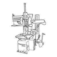
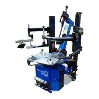
Identifies the key components of the wheel balancing machine.
Provides physical dimensions of the machine, including with the optional wheel guard.
Lists detailed specifications such as weight, power supply, and balancing speed.
Procedures and warnings for connecting the machine to the power supply.
Instructions for fitting the cone-type adapter for wheel fastening.
Guidelines for securely mounting wheels using manufacturer-provided adapters.
Steps for assembling and adjusting the optional wheel guard.
Information on using optional spacers for wide wheels.
Overview of the machine's control panel, buttons, and display indicators.
Explanation of the gauge used for automatic measurement of wheel distance and diameter.
Instructions on how to use the built-in gauge for weight application.
How the machine automatically detects the correct balancing program for different rim types.
Step-by-step guide for using Auto Select with steel rims.
Guide for using Auto Select with ALU M rims, including adhesive weight placement.
Instructions for using Auto Select with ALU 3M rims, covering clip-on and adhesive weights.
Using alternative ALU balancing modes not covered by Auto Select.
Understanding the unbalance readings and weight positioning indicators on the display.
Procedure to recalculate unbalance after making adjustments.
How to use the program for two operators to balance different wheels simultaneously.
Using the SPLIT function to position adhesive weights discreetly behind spokes.
Function to reduce weight needed for balancing and improve tyre eccentricity.
Explains different modes for balancing steel and alloy rims with various weight applications.
Details the MINISTAT function for reducing residual static unbalance intelligently.
Navigation and options within the machine's setup menu.
Running diagnostic tests for maintenance staff to check machine functions.
Procedure for performing machine self-calibration with a test wheel.
Procedures for calibrating automatic measurement gauges.
Steps to calibrate the automatic rim distance measurement gauge.
Procedure for calibrating the automatic wheel diameter measurement gauge.
Adjusting gauge settings for different adhesive weight application methods.
Troubleshooting steps for when the wheel balancer fails to rotate.
Diagnosing and resolving issues related to low wheel rotation speed during measurement.
Addressing errors indicating excessive unbalance detected by the machine.
Troubleshooting incorrect wheel rotation direction during operation.
Resolving errors caused by the safety guard not being properly closed.
Steps to fix errors related to reading non-volatile RAM parameters.
Troubleshooting excessive wheel speed detected during measurement.
Diagnosing various unbalance measurement errors and their potential causes.
Resolving issues where the wheel fails to rotate after the start command.
Troubleshooting motor running continuously beyond the allowed time.
Addressing errors when the maximum allowed number of measurement spins is exceeded.
Guidance for split function errors related to insufficient spoke distance.
Guidance for split function errors related to excessive spoke distance.
Troubleshooting split function errors when the first spoke is misplaced.
General advice for errors occurring during test functions.
Explains why wheels might show different unbalance readings on subsequent mountings.
Instructions for safely replacing the machine's fuses.
| Brand | Hofmann Megaplan |
|---|---|
| Model | EASY |
| Category | Tyre Changers |
| Language | English |