I 0667 - 6
5
6
16
1
2
4
3
17
10
13
15
14
12
11 8
9
7
GB
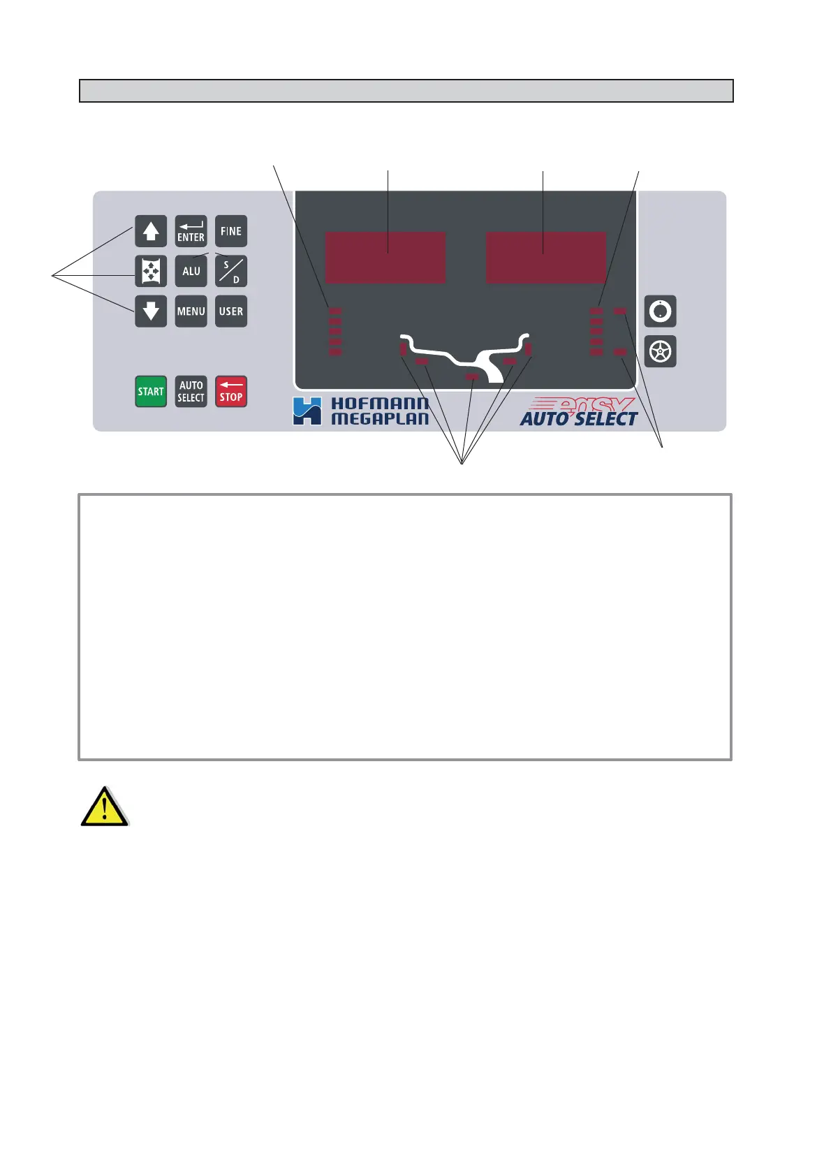
4 - CONTROLS AND COMPONENTS
4.1 - CONTROL PANEL AND DISPLAY
1-2 Digital readouts, AMOUNT OF UNBALANCE, inside/outside
3-4 Digital readouts, POSITION OF UNBALANCE, inside/outside
5 Indicators, correction mode selected
6 Indicators, selection made
7 Push button, unbalance reading < 5 g (25 oz)
8 Push button, operator selection
9 Push button, selection of manual correction modes
10 Push button, SPLIT (unbalance spread)
11 Push button, FUNCTIONS MENU
12 Push button, menu selection confi rmation
13 Push button, cycle start
14 Push button, emergency/home
15 Push button AUTO SELECT
16 Manual dimension setting buttons
17 Push button, unbalance optimization
O
N ▪ LY USE THE FINGERS TO PRESS THE PUSH BUTTONS.
N
EVER USE THE COUNTERWEIGHT PINCERS OR OTHER POINTED OBJECTS. ▪
4.2 - AUTOMATIC DISTANCE AND DIAMETER GAUGE
Allows automatic measurement of the distance from the machine and the wheel diameter at the counterweight
application point. The same gauge can be used to position the counterweights correctly inside the wheel, using the
specifi c function that suggests the position memorised during measurement inside the rim.