Do you have a question about the Hofmann geodyna 4900 and is the answer not in the manual?
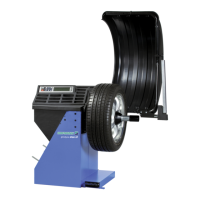
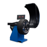
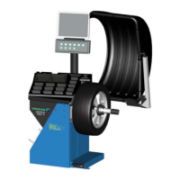
Official title of the document for the geodyna 4900 wheel balancer.
Legal text outlining warranty limitations and liability disclaimers.
Important introductory note urging careful reading of the manual for correct usage.
Covers essential safety guidelines and the fundamental functions of the wheel balancer.
Outlines general safety rules for operating the wheel balancer, emphasizing trained personnel and proper usage.
Details site selection, unpacking, and initial setup procedures for the machine.
Explains how to mount the wheel guard, width gauge arm, and connect cables.
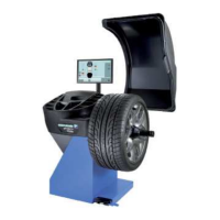
Guides on fitting and connecting the monitor and PC for the machine's interface.
Describes the function of each key on the machine's keypad for operation.
Details the screen layout, display zones, information fields, and menu fields.
Explains various pictographs and symbols used on the screen for different wheel and rim types.
Details various balancing modes and weight placement options on the rim.
Explains the gauge arms and visual indicators for unbalance and correction positions.
Details procedures for fitting tyres, rotating rims, and aligning marks with the valve.
Identifies the tyre changer tool used in the process.
Explains the structure and purpose of screen menus.
Lists the functions accessible from the main menu via F1 to F5 keys.
Explains menu functions for balancing, including data input, unbalance selection, and spoke placement.
Covers inputting rim dimensions and selecting wheel profiles via menu keys.
Details selecting weight positions for the left and right correction planes.
Explains how to access user calibration, text editor, and change function values or modes.
Guides the user through selecting the wheel type using menu keys F1-F5.
Details how to select weight positions on the rim for the left and right correction planes.
Explains how to input rim dimensions, including distance, width, and diameter.
Covers manual and automatic methods for measuring and entering rim width.
Illustrates correct gauge head positions for different wheel types and weight placements.
Details specific weight placement types and their characteristics for various wheel categories.
Explains how to determine exact correction dimensions (AP1, AP2) for Alu 3P wheels.
Explains how to fit balance clips for position AP1 as a spring weight.
Details the procedure for fitting adhesive weights for position AP2.
Lists necessary preparations and shows the BALANCING screen layout with menu keys.
Explains how to start a measurement run from different screens.
Details the procedure for fitting balance clips to the left and right correction planes.
Details fitting adhesive weights based on entered dimensions when gauge head access is not possible.
Explains how to start a check run after fitting balance weights to verify the result.
Describes how to measure and display static unbalance using menu key F3.
Explains the purpose and basic procedure of the behind-the-spokes placement program for spoked wheels.
Details how to select the behind-the-spokes mode and input rim data via menu keys.
Details the process of correcting measured unbalance using the behind-the-spokes method.
Explains how to fit adhesive weights on the left side of the rim disc and hidden weights.
Explains how to return to the undivided display of unbalance for left and right correction planes.
Details how to exit behind-the-spokes mode and reset the unit to conventional balancing.
Provides important notes and considerations for using the behind-the-spokes placement program.
Explains how to access the FUNCTIONS screen and lists menu key assignments.
Details how to select, change values of, and confirm operating modes.
Explains how to permanently save changed operating modes to the machine's memory.
Details available modes, language selection, and audible signal volume settings.
Configures display resolution for unbalance readings and suppression of minor values.
Sets the threshold for suppressing small unbalances and selects measurement units (grams/ounces).
Configures the number of measurement turns per run and notes its impact on accuracy.
Configures starting the measuring run by closing the wheel guard instead of the START button.
Controls whether the wheel is automatically braked when the wheel guard is raised.
Allows setting the current date and time, which are immediately active.
Guides on entering text character by character using cursor keys and transfer functions.
Explains how to save entered text to permanent memory or discard changes.
Categorizes error messages into E-Meldung (operation errors), H-Meldung (warnings), and Fatal errors.
Lists and explains specific error codes related to data input, wheel guard, gauge arms, compensation, and calibration.
Details errors occurring during optimisation or minimisation procedures.
Explains errors related to readjustment range, calibration weight, and wheel slip.
Explains errors related to unusable measurement data and main shaft speed limits.
Details errors concerning jammed keys and defective gauge arms.
Explains optimisation as matching rim/tyre, reducing forces, and minimising balance weight.
Provides guidance on using optimisation/minimisation programs, including interruption and continuation.
Covers initial checks, wheel clamping, data entry, and accessing optimisation menus.
Details starting weight minimisation or optimisation procedures via menu keys.
Details tyre turning, wheel clamping, valve positioning, and starting measurement for optimisation.
Explains how to handle error code E9 by aborting and restarting the optimisation program.
Explains final status readings like OK, H0, or H2 after optimisation/minimisation.
Details how to return to the BALANCING screen using menu keys F1 or F6.
States that the balancer requires minimal maintenance, with particular attention to the shaft cone and clamping means.
Provides contact details for after-sales service in Germany.
Lists overall machine dimensions, weight, power, motor, speed, and environmental specs.
Details the operating range for distance, rim width, diameter, max wheel dimensions, and weight.
Declares conformity to EC directives for machines and EMC, listing applied standards.
States conditions under which the declaration becomes void, such as improper use or modifications.
| Balancing Speed | 200 rpm |
|---|---|
| Balancing Accuracy | ± 1 g |
| Weight | 120 kg |
| Rim Width | 1.5" - 20" |
| Rim Diameter | 8" - 30" |
| Wheel Width | 1.5 - 20 inches |
| Wheel Diameter | 10 - 30 inches |
| Wheel Diameter Range | 10 - 30 inches |
| Wheel Width Range | 1.5 - 20 inches |
| Power Supply | 230V 1Ph 50/60 Hz |