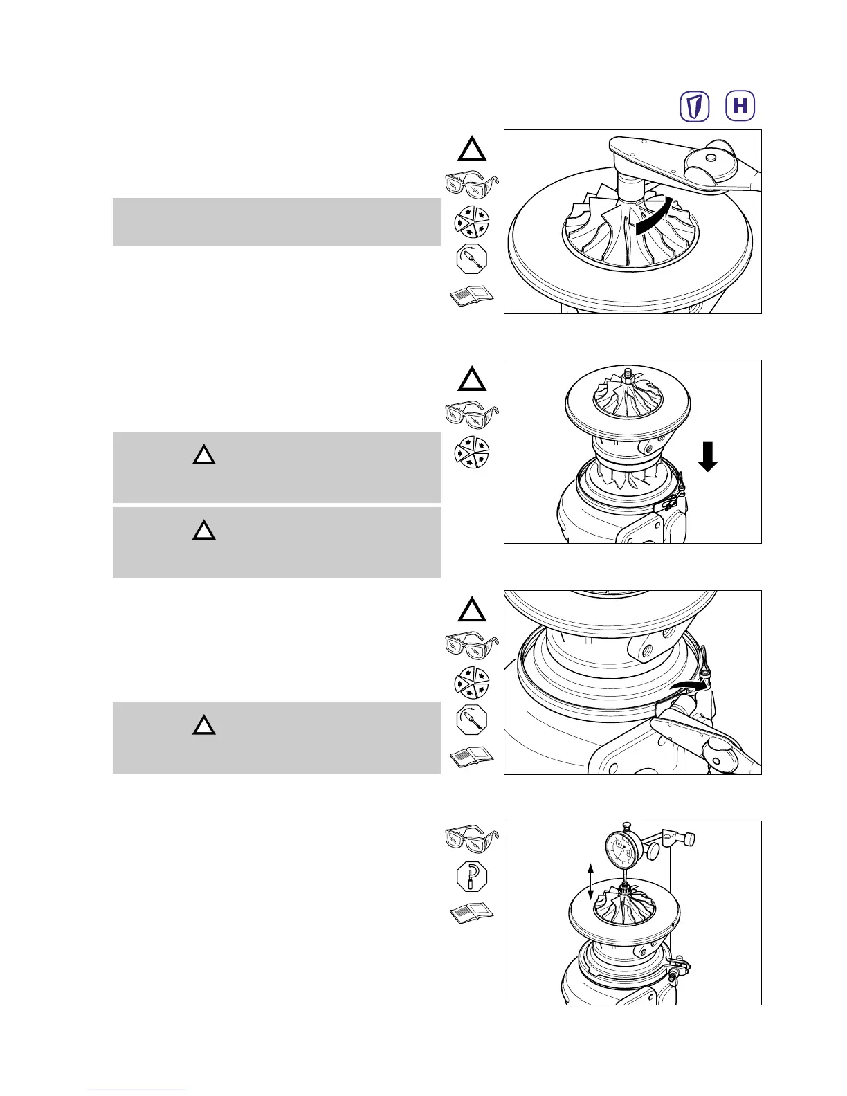
M7 LH (10 mm)
Install the new locknut, compressor wheel (61) and
tighten in two stages to the values shown in the
Service Data Sheet.
HX25/25W/27W Service Repair Manual Turbocharger Service and Overhaul
5:17
Place turbine housing (5) on a clean surface. Place v-
band (28) loosely into position on the turbine housing.
Carefully slide CHRA (2) assembly into the turbine
housing. Use alignment marks to locate CHRA
assembly onto the dowel pin located in the turbine
housing.
M6 (10 mm)
Apply molycote anti-seize compound to threads of
locknut, v-band (62) and tighten to the value specified
in the Service Data Sheet.
Ensure rotor assembly freely rotates.
Check thrust clearance using a dial gauge. Ensure
clearance is within MIN/MAX values shown on
Service Data Sheet.
Note
Left hand thread.
Caution
The compressor wheel blades can be easily damaged
when the CHRA is installed.
Caution
Be careful not to bend the location pin during
assembly.
Caution
Be careful not to bend the location pin during
assembly.