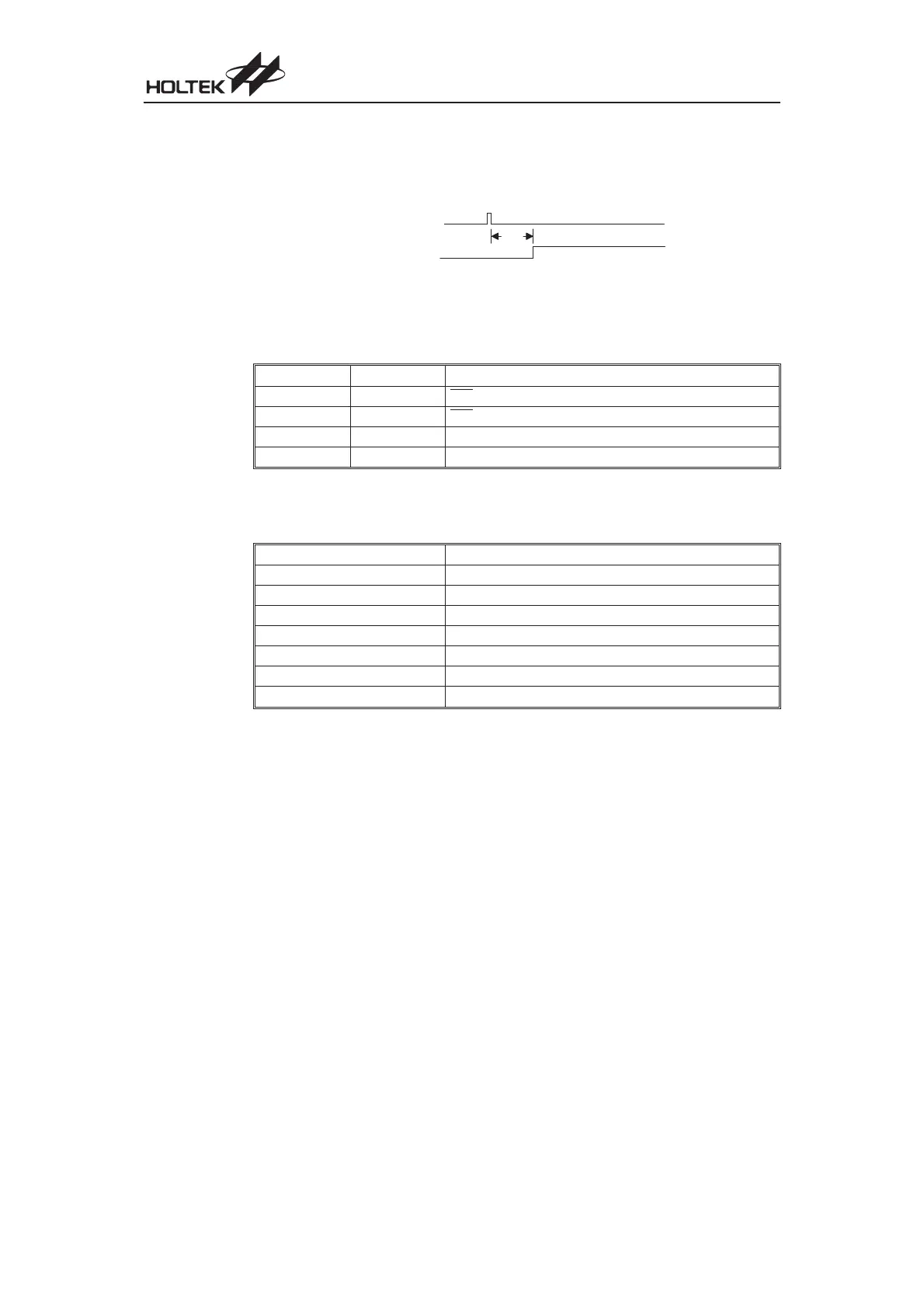
Watchdog Time-out Reset during HALT
The Watchdog time-out reset during HALT is a little different from other kinds of reset. Most of the
conditions remain unchanged except that the Program Counter and the Stack Pointer will be
cleared to 0 and the TO flag will be set to 1. Refer to A.C. Characteristics for t
SST
details.
The different types of resets described affect the reset flags in different ways. These flags known
as PDF and TO are located in the status register and are controlled by various microcontroller op
-
erations such as the halt function or Watchdog Timer. The reset flags are shown below:
TO PDF RESET Conditions
0 0 RES
reset during power-on
u u RES
or LVR reset during normal operation
1 u WDT time-out reset during normal operation
1 1 WDT time-out reset during HALT
²u² stands for unchanged
The table indicates the way in which the various components of the microcontroller are affected af
-
ter a power-on reset occurs.
Item Condition After RESET
Program Counter Reset to zero
Interrupts All interrupts will be disabled
WDT Clear after reset, WDT begins counting
Timer/Event Counter All Timer Counters will be turned off
Prescaler The Timer Counter Prescaler will be cleared
Input/Output Ports All I/O ports will be setup as inputs
Stack Pointer Stack Pointer will point to the top of the stack
Cost-Effective I/O Type MCU
36
W D T T i m e - o u t
S S T T i m e - o u t
t
S S T
WDT Time-out Reset during HALT Timing Chart
 Loading...