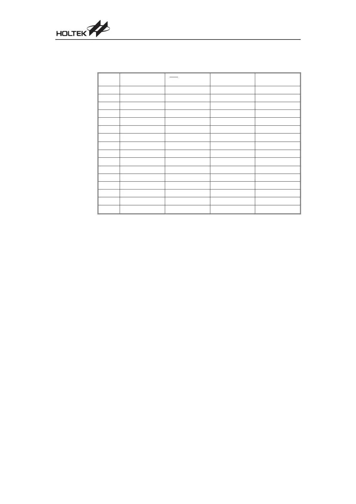
The different kinds of reset all affect the internal registers of the microcontroller in different ways.
To ensure reliable continuation of normal program execution after a reset occurs, it is important to
know what condition the microcontroller is in after a particular reset occurs. The following table de
-
scribes how each type of reset affects each of the
microcontroller
internal registers.
Register Reset (Power-on) RES or LVR Reset
WDT Time-out
(Normal Operation)
WDT Time-out
(HALT)
MP
- xxx xxxx - uuu uuuu - uuu uuuu - uuu uuuu
ACC xxxx xxxx uuuu uuuu uuuu uuuu uuuu uuuu
PCL 0000 0000 0000 0000 0000 0000 0000 0000
TBLP xxxx xxxx uuuu uuuu uuuu uuuu uuuu uuuu
TBLH
- - xx xxxx --uu uuuu --uu uuuu --uu uuuu
WDTS 0000 0111 0000 0111 0000 0111 uuuu uuuu
STATUS
- - 00 xxxx - - uu uuuu - - 1u uuuu - - 11 uuuu
INTC
- - 00 - 000 - - 00 - 000 - - 00 - 000 --uu - uuu
TMR xxxx xxxx xxxx xxxx xxxx xxxx uuuu uuuu
TMRC
00- 0 1000 00- 0 1000 00- 0 1000 uu- u uuuu
PA 1111 1111 1111 1111 1111 1111 uuuu uuuu
PAC 1111 1111 1111 1111 1111 1111 uuuu uuuu
PB 1111 1111 1111 1111 1111 1111 uuuu uuuu
PBC 1111 1111 1111 1111 1111 1111 uuuu uuuu
PC
---- -111 ---- -111 ---- -111 - - - - - uuu
PCC
---- -111 ---- -111 ---- -111 - - - - - uuu
²u² stands for unchanged
²x² stands for unknown
²-² stands for unimplemented
Chapter 1 Hardware Structure
37