Rev. 1.71 80 April 11, 2017 Rev. 1.71 81 April 11, 2017
HT66F002/HT66F0025/HT66F003/HT66F004
Cost-Effective A/D Flash MCU with EEPROM
HT66F002/HT66F0025/HT66F003/HT66F004
Cost-Effective A/D Flash MCU with EEPROM
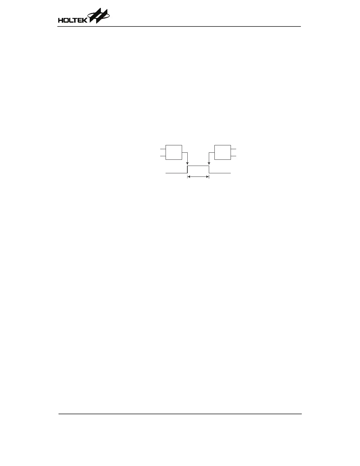
Single Pulse Mode
Toselectthismode,bitsST0M1andST0M0intheSTM0C1registershouldbesetto10
respectivelyandalsotheST0IO1andST0IO0bitsshouldbesetto11respectively.TheSinglePulse
OutputMode,asthenamesuggests,willgenerateasingleshotpulseontheSTMoutputpin.
ThetriggerforthepulseoutputleadingedgeisalowtohightransitionoftheST0ONbit,which
canbeimplementedusingtheapplicationprogram.HoweverintheSinglePulseMode,theST0ON
bitcanalsobemadetoautomaticallychangefromlowtohighusingtheexternalSTCK0pin,
whichwillinturninitiatetheSinglePulseoutput.WhentheST0ONbittransitionstoahighlevel,
thecounterwillstartrunningandthepulseleadingedgewillbegenerated.TheST0ONbitshould
remainhighwhenthepulseisinitsactivestate.Thegeneratedpulsetrailingedgewillbegenerated
whentheST0ONbitisclearedtozero,whichcanbeimplementedusingtheapplicationprogramor
whenacomparematchoccursfromComparatorA.
S/W Command
SET“ST0ON”
or
STCK0 Pin
Transition
Trailing Edge
S/W Command
CLR“ST0ON”
or
CCRA Compare
Match
STP0/STP0B Output Pin
Pulse Width = CCRA Value
Leading Edge
ST0ON bit
0 → 1
ST0ON bit
1 → 0
Single Pulse Generation