22 KGZ Series | Version 2.02 | EN
Operation the Chop- and Mitre Saw
8.2.3Cross cutting (Model KGZ 255 E)
For cutting widths up to approx. 100 mm, it is possible to
fix the saw-pulling function with the locking screw (22) for
the return of the pulling aid. If the cutting width exceeds
100 mm, loosen the locking screw (22) for the pulling aid
and the machine head (19) can be removed.
Step 1: Move the machine head (19) into the
upper position.
Step 2: Insert the machine head (19) with the handle (1)
to the rear and fix it in this position if necessary
(depending on the cutting width).
Step 3: Place the piece of wood to be cut against the
workpiece stop (15) and on the turntable (25).
Attention! Clamp the material on the fixed saw
table with the clamp (13) to prevent the material
from moving during the cutting process.
Step 4: Flat material in a lying position with the
tension the vertical clamping device.
Step 5: Turn on the saw: Press the
Key lock (24) to the left, and hold
press the on / off button (2).
Step 6: With fixed guide: Use the handle (1) to move the
machine head (19) down evenly and with light
pressure until the saw blade (18) has completely
cut through the workpiece.
Step 7: When the tow guide is not fixed: Pull the machine
head (19) all the way to the front and move it with
the handle (1) evenly and with a slight downward
pressure. Now push the machine head (19) back
slowly and evenly until the saw blade (18) has
completely cut through the workpiece.
Step 8: When the cutting process is complete, move the
machine head (19) back to its upper (home) po-
sition and release the on / off button (2) to turn off
the saw. Important! The integrated return springs
lift the machine head automatically. Do not
simply release the handle (1) after cutting, but let
the machine head (19) rise slowly, applying
slight counterpressure.
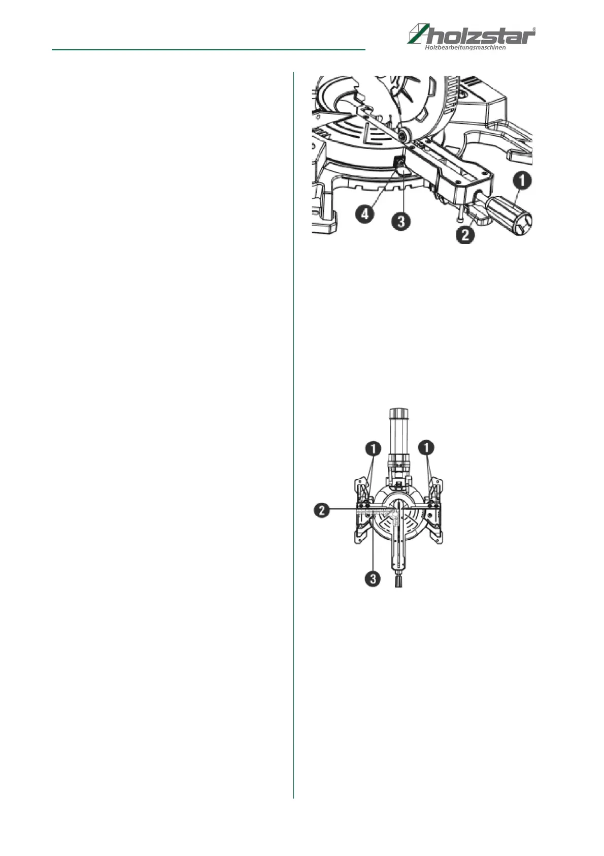
8.2.4Adjustment of the Mitre Angle Pointer
(Model KGZ 255 E)
Step 1: Move the table to the 0° positive stop.
Fig. 9: Adjustment of the mitre angle pointer
Step 2: Loosen the screw (Pos. 4) that holds the indica-
tor with a Phillips screwdriver.
Step 3: Adjust the indicator (Pos. 3) to the 0° mark and
retighten the screw.
8.2.5Adjusting the Fence (Model KGZ 255 E)
Step 1: Lower the cutting head and lock in position
Fig. 10: Adjusting the Fence
Step 2: Remove the fixing screws and then pull out the
left and right upper sliding fences (Pos. 2). Four
fence locking bolts (Pos. 1) will appear.
Step 3: Lower the cutting head and lock it in position.
Step 4: Using a square (Pos. 3 lay the heel of the square
against the blade and the ruler against the fence
(Pos. 2) as shown.
Step 5: Loosen the four fence locking bolts with a 4 mm.
hex wrench.