c.
ASSEMBLY
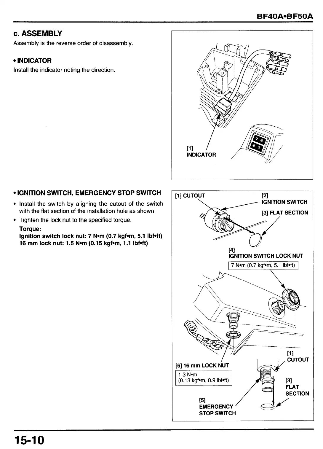
Assembly is the reverse order of disassembly.
INDICATOR
Install the indicator noting the direction.
IGNITION SWITCH, EMERGENCY STOP SWITCH
Install the switch by aligning the cutout of the switch
with the flat section
of
the installation hole as shown.
Tighten the lock nut to the specified torque.
Torque:
Ignition switch lock nut:
7
N*m
(0.7
kgfom, 5.1 Ibf*ft)
16 mm lock nut: 1.5 N*m (0.15 kgf*m, 1.1 Ibfuft)
[l] CUTOUT 121
IGNITION SWITCH
FLAT SECTION
t41
IGNITION SWITCH LOCK NUT
I
7
N*m
(0.7
kgf*rn,
5.1
Ibfoft)
I
/
[6]
16
mm
LOCK NUT
1.3
N*m
CUTOUT
[31
FLAT
SECTION
PI
EMERGENCY
Y
STOP SWITCH
15-1
0