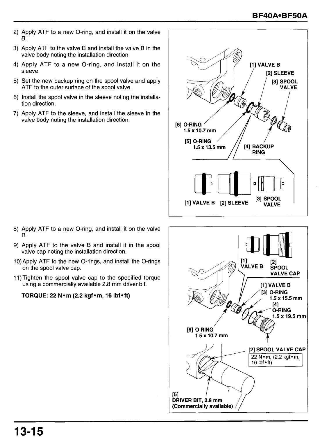
2)
Apply ATF to a new O-ring, and install it on the valve
3)
Apply ATF to the valve
B
and install the valve
B
in the
4)
Apply ATF to a new O-ring, and install it on the
5)
Set the new backup ring on the spool valve and apply
6)
Install the spool valve in the sleeve noting the installa-
7)
Apply ATF to the sleeve, and install the sleeve in the
€3.
valve body noting the installation direction.
sleeve.
ATF to the outer surface of the spool valve.
tion direction.
valve body noting the installation direction.
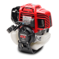
8)
Apply ATF to a new O-ring, and install it on the valve
9)
Apply ATF to the valve
B
and install it in the spool
10)Apply ATF to the new O-rings, and install the O-rings
11)Tighten the spool valve cap to the specified torque
6.
valve cap noting the installation direction.
on the spool valve cap.
using a commercially available
2.8
mm driver bit.
TORQUE:
22
N*m
(2.2
kgf*m,
16
Ibf*ft)
[l]
VALVE
B
/
[2]SLEEVE
1.5
x
10.7
’/
mm
[6]
O-RING
[3]
SPOOL
/
1
VALVE
/
//
141
EfNcKUP
1.5
x
13.5
mm
[5]
O-RING
/
-/
~~
VALVE CAP
7
.
-r
[l]
VALVE
B
1.5
x
15.5
[3]
O-RING
1.5
x
10.7
mm
mm
.5
mm
151
DRIVER BIT, 2.8
mm
(Commercially available)
151
DRIVER BIT, 2.8
mm
(Commercially available)
13-1
5