f.
BLOW
PRESSURE
INSPECTION
After reassembling the power trim/tilt assembly, per-
form the blow pressure inspection. Install the power
trimhilt assembly after the blow pressure inspection.
Remove the power trim/tilt assembly if it is mounted.
Before blow pressure inspection, perform the following:
-
Connect each engine side wire and motor
2P
con-
nector
so
that the power trimhilt assembly can oper-
ate while it is isolated from the outboard motor.
-
Extend the piston rod of the power trim/tilt assembly
fully after operating (moving up and down) the pis-
ton rod several times.
-
Check ATF level in the power trimhilt assembly oil
tank. It must be at the specified level (P. 13-28).
-
Perform the cylinder upper chamber side and lower
chamber side blow pressure inspection using the
special
tools
and commercially available pressure
gauge.
-
Use the pressure gauge which measures 40 MPa
(400 kgf/cm2,
5,600
psi) or above with P/F 1/4
thread.
LOWER CHAMBER
SIDE
BLOW PRESSURE
1) Remove the internal circlip, manual valve and sealing
washer from the valve body. Install the special
tool
(gauge joint body B) and the sealing washer, and
tighten the special tool to the specified torque.
TORQUE:
1.7 N*m (0.17 kgf*m, 1.2 Ibf*ft)
Be sure to remove the manual valve with the piston
rod fully extended, or ATF spurts out.
A
small amount of ATF flows out after removing the
valve. Install the special
tool
quickly.
Install the sealing washer securely not
to
let it col-
lapse in the valve body.
2)
Attach a commercially available pressure gauge
to
the special
tool
that is set in the valve body.
3) Be sure that ATF level in the oil tank
is
at the speci-
fied level
(P.
13-28).
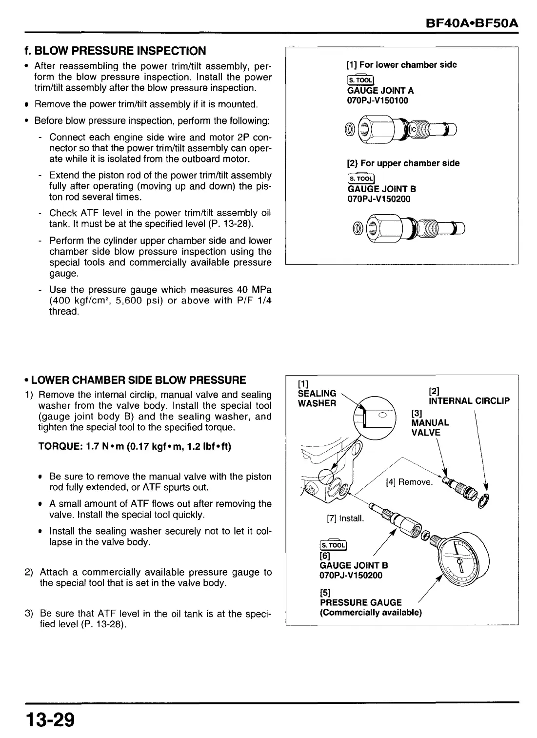
[l]
For lower chamber side
[s.TooJ
GAUGE JOINT A
07OPJ-V150100
[2}
For upper chamber side
[S.]
GAUGE JOINT
B
07OPJ-V150200
INTERNAL
ClRCLlP
07OPJ-V150200
[51
PRESSURE GAUGE
/
(Commercially available)
13-29