44
4. ENGINE
Fig.
125 (j) Gear shift drum ® Micrometer
Fig. 126 (j) Gear shift fork ® Micrometer
Fig. 127 (j) Gear shift forks ® Gear shift drum
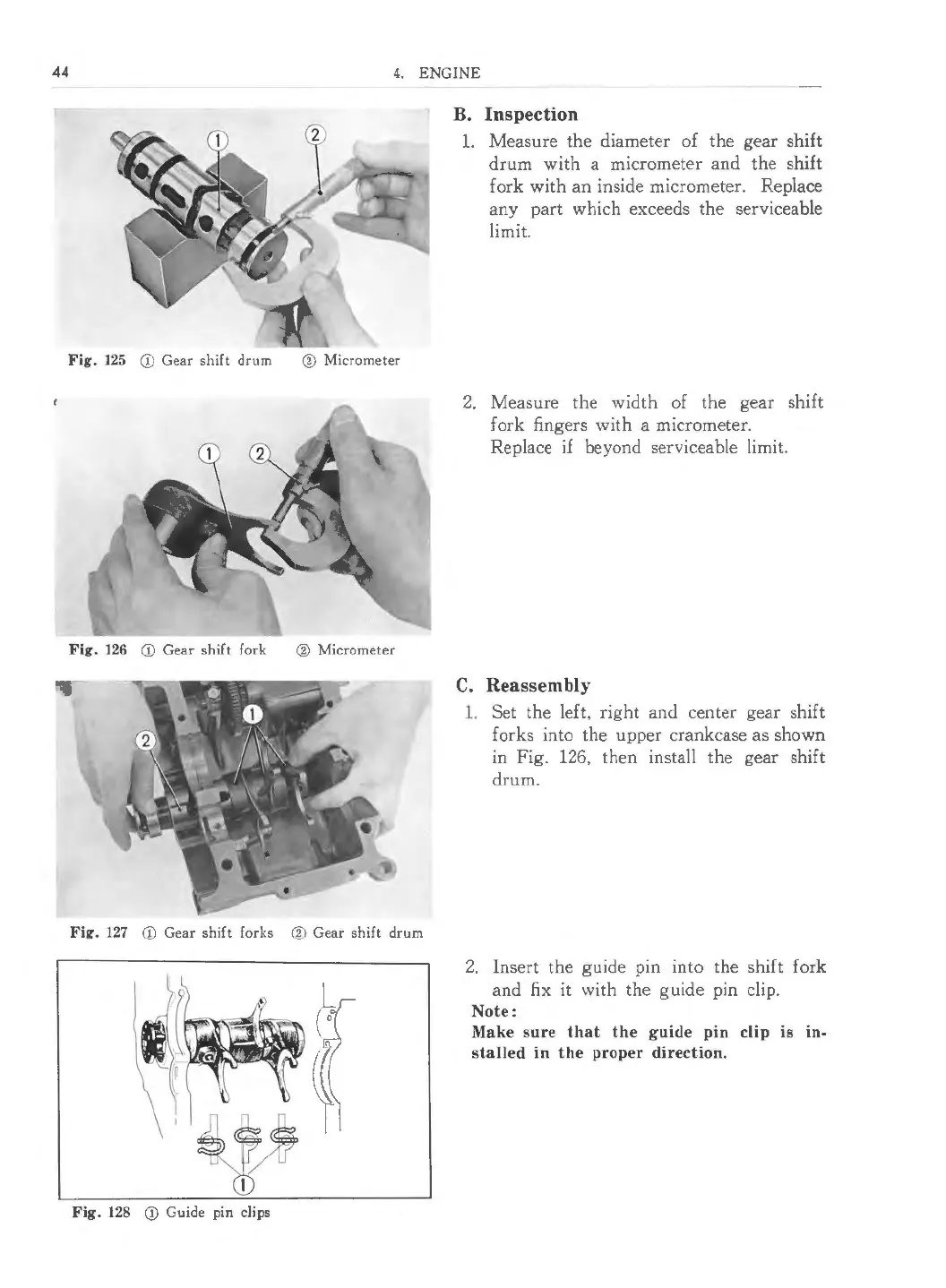
Fig. 128 (j) Guide pin clips
B. Inspection
1. Measure the diameter of the gear shift
drum with a micrometer and the shift
fork with an inside micrometer. Replace
any part which exceeds the serviceable
limit.
2. Measure the width of the gear shift
fork fingers with a micrometer.
Replace if beyond serviceable limit.
C. Reassembly
1. Set the le£ t, right and center gear shift
forks into the upper crankcase as shown
in Fig. 126, then insta ll the gear shift
drum.
2. Insert the guide pin into the shift fork
and fix it with the guide pin clip.
Note :
Make sure that the guide pin clip is in-
sta lled in the proper directio n.
 Loading...