4. ENGINE
45
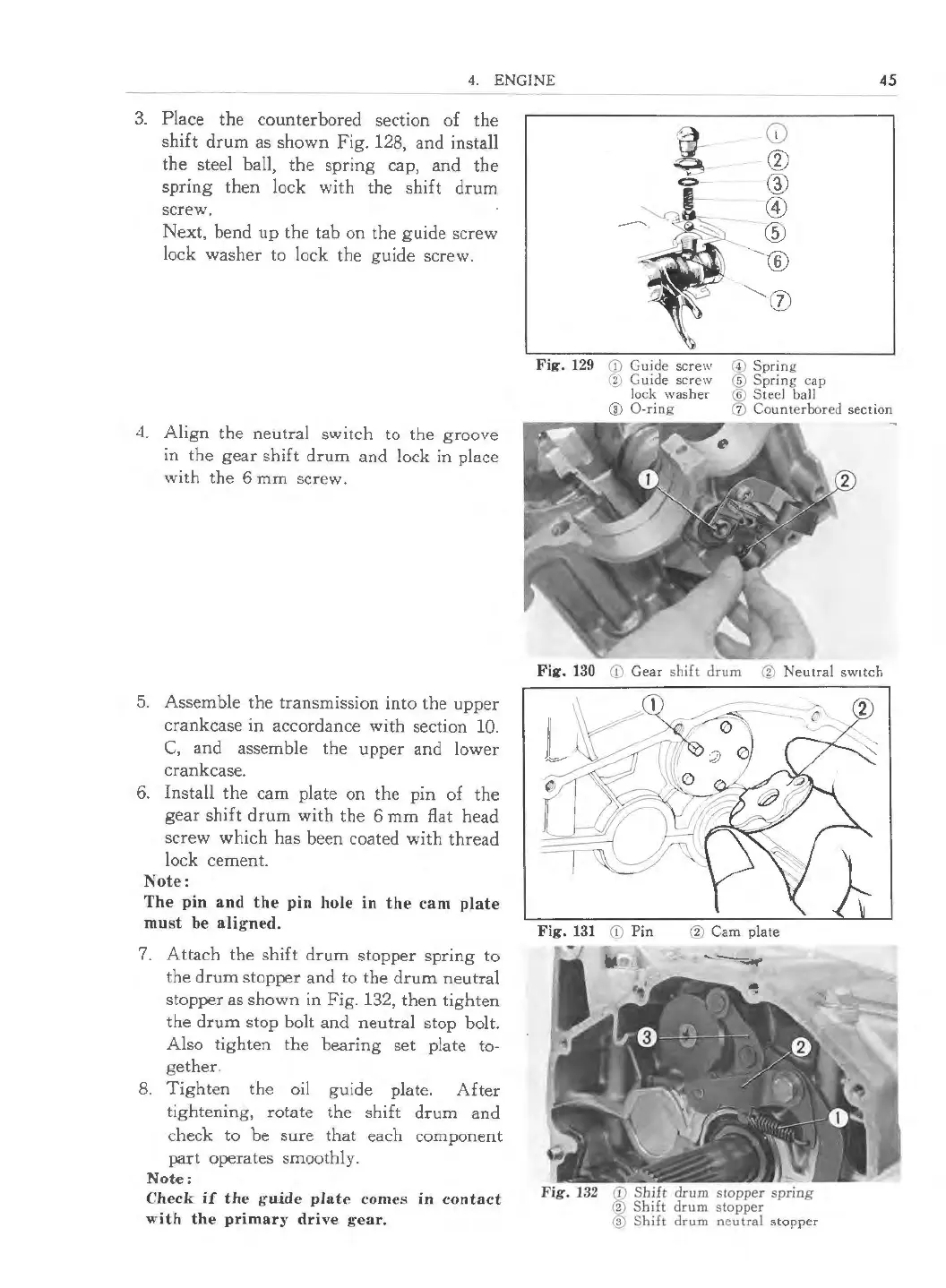
3. Place the counterbored section of the
shift drum as shown Fig. 128, and install
the steel ball, the spring cap, and the
spring then lock with the shift drum
screw.
Next, bend up the tab on the guide screw
lock washer to lock the guide screw.
4. Align the neutral switch to the groove
in the gear shift drum and lock in place
with the 6 mm screw.
5. Assemble the transmission into the upper
crankcase in accordance with section 10.
C, and assemble the upper and lower
crankcase.
6. Install the cam plate on the pin of the
gear shift drum with the 6 mm flat head
screw which has been coated with thread
lock cement.
Note:
The pin and the pin hole in the cam plate
must be ali gned.
7. Attach the shift drum stopper spring to
the drum stopper and to the drum neutral
stopper as shown in Fig. 132, then tighten
the drum stop bolt and neutral stop bolt.
Also tighten the bearing set plate to·
gether.
8. Tighten the oil guide plate. After
tightening, rotate the shift drum and
check to be sure that each component
part operates smooth ly.
Note:
Check if the guide plate comes in contact
with the primary drive gea r.
*
c:>-
Fig. 129 <D Guide screw
'V Guide screw
lock washer
@ 0-ring
G)
®
®
©
--
®
®
(J)
© Spring
® Spring cap
® Steel ball
(1) Counterbored section
Fig. 130 <D Gear shift drum ® Neutral switch
Fig. 131 (D Pin @ Cam plate
Fig. 132 CD Shift drum stopper spring
@ Shift drum stopper
@ Shift drum neutral stopper
 Loading...