48
4. ENGINE
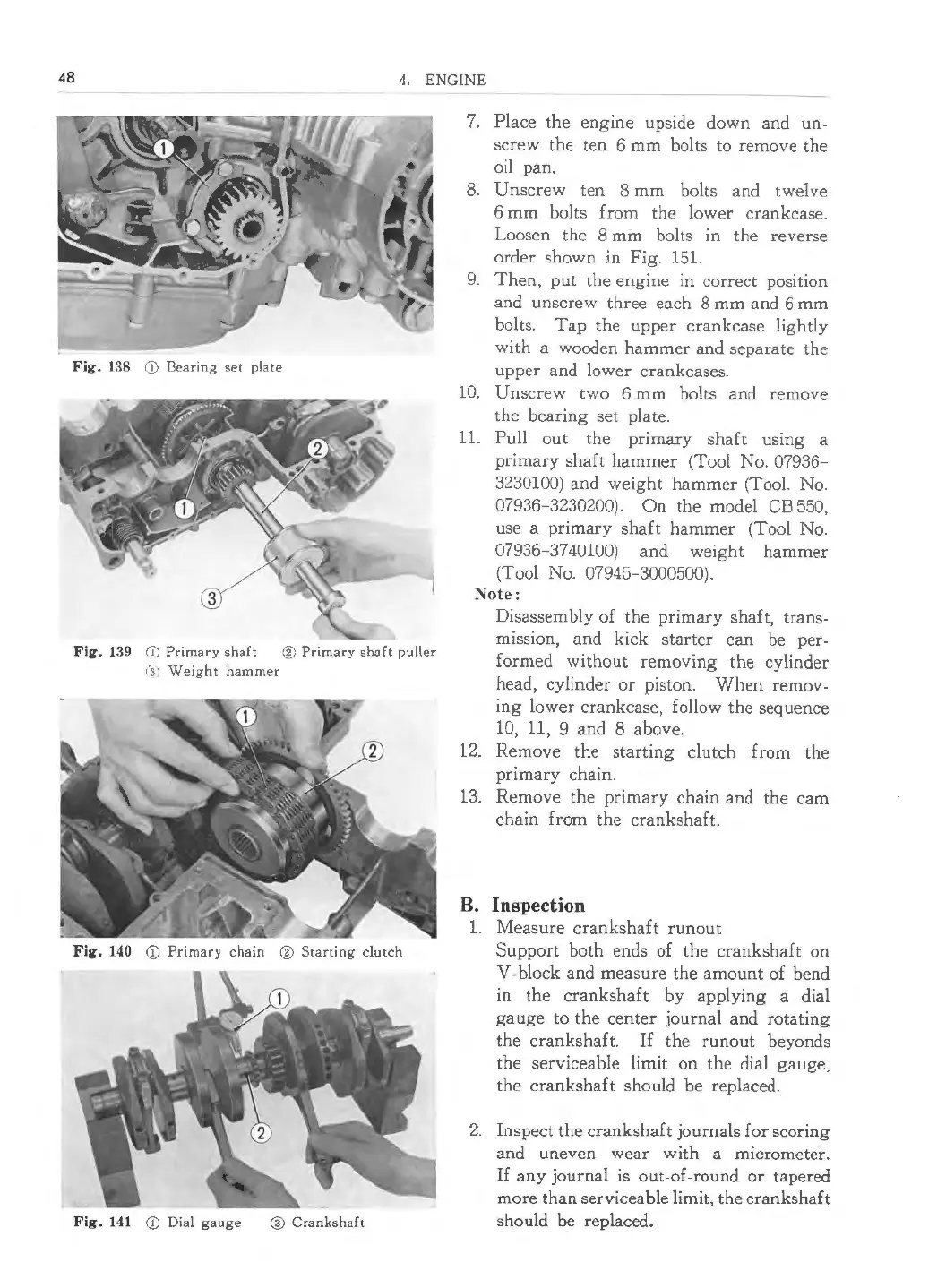
Fig. 138 CD I3earing set plate
Fig . 139 (i) Primary shaft ® Primary shaft puller
3 Weight hammer
Fig . 140 <D Primary chain ® Starting clutch
Fig . 141 <D Dial gauge ® Crankshaft
7. Place the engine upside down and un-
screw the ten 6 mm bolts to remove the
oil pan.
8. Unscrew ten 8 mm bolts and twelve
6 mm bolts from the lower crankcase.
Loosen the 8 mm bolts in the reverse
order shown in Fig. 151.
9. Then, put the engine in correct position
and unscrew three each 8 mm and 6 mm
bolts. Tap the upper crankcase lightly
with a wooden hammer and separate the
upper and lower crankcases.
10. Unscrew two 6 mm bolts and remove
the bearing set plate.
11. Pull out the primary shaft using a
primary shaft hammer (Tool No.
07936-
3230100)
and weight hammer (Tool. No.
07936-3230200). On the model CB 550,
use a primary shaft hammer (Tool No.
07936-3740100) and weight hammer
(Tool No.
07945-3000500).
Note:
Disassembly of the primary shaft, trans-
mission, and kick starter can be per-
formed without removing the cylinder
head, cylinder or piston. When remov-
ing lower crankcase, follow the sequence
10, 11, 9 and 8 above.
12. Remove the starting clutch from the
primary chain.
13. Remove the primary chain and the cam
chain from the crankshaft.
B. Inspection
1. Measure crankshaft run out
Support both ends of the crankshaft on
V-block and measure the amount of bend
in the crankshaft by applying a dial
gauge to the center journal and rotating
the crankshaft.
If the runout beyonds
the serviceable limit on the dial gauge,
the crankshaft should be replaced.
2. Inspect the crankshaft journals for scoring
and uneven wear with a micrometer.
If any journal is out-of -round or tapered
more than serviceable limit, the cranks ha£
t
should be replaced.
 Loading...