4. ENGINE
49
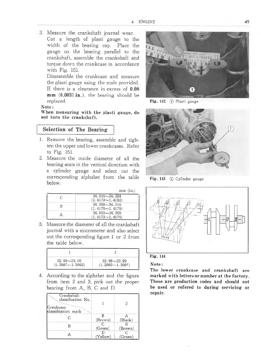
3. Measure the crankshaft journal wear.
Cut a length of plasti gauge to the
width of the bearing cap. Place the
gauge on the bearing parallel to the
crankshaft, assemble the crankshaft and
torque down the crankcase in accordance
with Fig.
151.
Disassemble the crankcase and measure
the plasti gauge using the scale provided.
If there is a clearance in excess of 0.08
mm (0.0031 in. }, the bearing should be
replaced.
Note:
When measuring with the plasti gauge, do
not turn the crank shaf t.
Selection of The Bearing
1. Remove the bearing , assemble and tigh-
ten the upper and lower crankcases. Refer
to Fig.
151.
2. Measure the inside diameter of all the
bearing seats in the vertical direction with
a cylinder gauge and select out the
corresponding alphabet from the table
below.
C
B
A
mm (in.)
36.016-36.024
(1.4179-1.4182 )
36. 008-36.016
(1.4176-1.4179 )
36.000-36.008
{l.4173-1.4176 )
3. Measure the diameter of all the crankshaft
journal with a micrometer and also select
out the correspond ing figure 1 or 2 from
the table below.
32.99-33. 00
{1.2987-1.2992 )
2
32.98-32. 99
{1.2983-1 .2987)
4. According to the alphabet and the figure
from item 2 and 3, pick out the proper
bearing from A, B, C and D.
~
Cranks haft
classification No.
1 2
Crankcase
classification mark
........,_
--
B A
C
{Brown)
(Black)
-
B
- c-
B
-
JQ.:een)
{Brown)
A
D C
(Yellow) (Green)
Fig . 142 CD Plasti gauge
Fig. 143 CD Cylinder gauge
Fig. 144
Note:
The lower crankca se and crank shaft are
mark ed with letter s or number at the factor y.
The se ar e production codes and should not
be used or refered to during servicing or
repair .
 Loading...