52
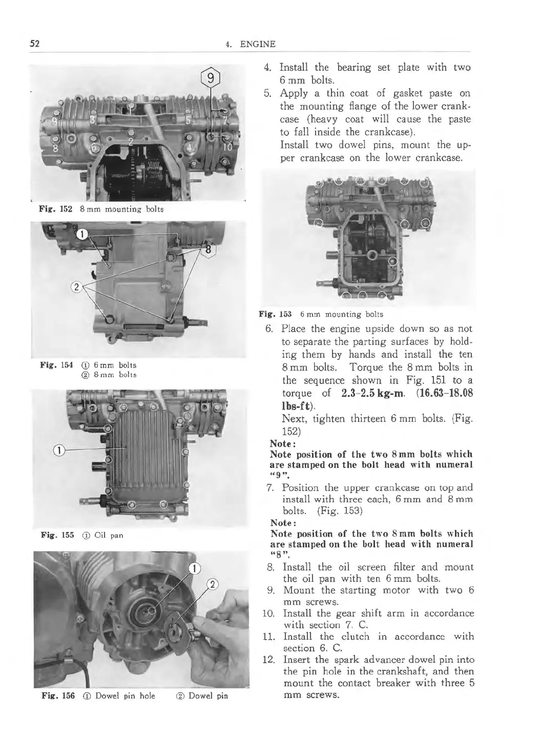
Fig . 152 8 mm mounting bolts
Fig. 154 CD 6 mm bolts
@ 8mm bolts
Fig . 155 CD Oil pan
Fig. 156 CD Dowel pin hole
4. ENGINE
@ Dowel pin
4. Install the bearing set plate with two
6 mm bolts.
5. Apply a thin coat of gasket paste on
the mounting flange of the lower crank-
case (heavy coat will cause the paste
to fall inside the crankcase ).
Install two dowel pins, mount the up-
per crankcase on the lower cran kcase.
Fig. 153 6 mm mounting bolts
6. Place the engine upside down so as not
to separate the parting surfaces by hold-
ing them by hands and install the ten
8 mm bolts. Torque the 8 mm bolts
in
the sequence shown in Fig. 151 to a
torque of
2.3-2.5 kg-m . (16.63-18.08
lbs-ft ).
Nex t, tighten thirteen 6 mm bolts. (Fig.
152)
Note:
Note position of the two 8 mm bolts which
are stamped on the bolt head with numeral
"9 ".
7. Position the upper crankcase on top and
install with three each, 6 mm and 8 mm
bolts. (Fig. 153)
Note:
Note position of the two 8 mm bolts which
are stamped on the bolt head with numeral
"8 ".
8. Insta ll the oil screen filter and mount
the oil pan with ten 6 mm bolts.
9. Mount the starting motor with two 6
mm screws.
10. Install the gear shift arm in accordance
with section 7. C.
11. Install the clutch in accordance with
section 6. C.
12. Insert the spark advancer dowel pin into
the pin hole in the crankshaft, and then
mount the contact breaker with three 5
mm screws.
 Loading...