4. ENGINE
9. Install the dust plate A, and mount the
adjuster holder to the link arm.
10. Insert the coil spnng B and tighten it
with the cap nut.
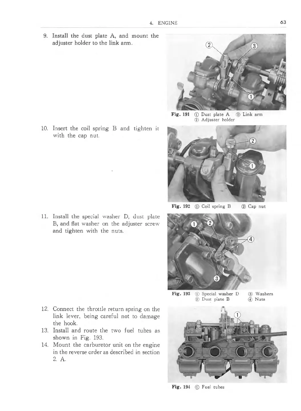
11. Install the special washer D, dust plate
B, and flat washer on the adjuster screw
and tighten with the nuts.
12. Connect the throttle return spring on the
link lever, being careful not to damage
the hook.
13. Install and route the two fuel tubes as
shown in Fig. 193.
14. Mount the carburetor unit on the engine
in the reverse order as described in section
2. A.
Fig . 191 (D Dust plate A ® Link arm
® Adjuster holder
Fig . 192 (D Coil spring B
Fig . 193 (D Special washer D
® Dust plate B
Fig. 194 (D Fuel tubes
@ Cap nut
® Washers
© Nuts
63
 Loading...