72
5. CHASSIS
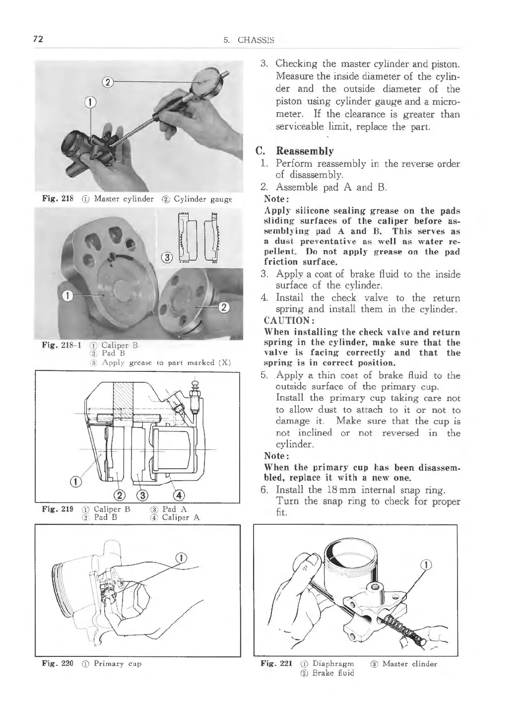
Fig. 218
Q Master cylinder @ Cylinder gauge
Fig. 218-1 'D Caliper B
ti Pad B
3 Apply grease to part marked (X)
Fig. 219 (!) Caliper B
(2 Pad B
Fig. 220
Cf\ Primary cup
@ Pad A
© Caliper A
3. Checking the master cylinder and piston.
Measure the inside diameter of the cylin-
der and the outside diameter of the
piston using cylinder gauge and a micro-
meter.
If the clearance is greater than
serviceable limit, replace the part.
C. Reassembly
1. Perform reassembly m the reverse order
of disassembly.
2. Assemble pad A and B.
Note:
Apply silicone sealin g grease on the pads
sliding surface s of the caliper before as-
semblying pad A and B. Thi s serve s as
a dust preventative as well as water re-
pellent. Do not apply grease on the pad
friction surface.
3. App ly a coat of brake fluid to the inside
surface of the cylinder.
4. Instail the check valve to the return
spring and install them in the cylinder.
CAUTION:
When installin g the check valve and return
spring in the cylinder, make sure that the
val ve is facing correctly and that the
spring· is in correct position.
5. Apply a thin coat of brake fluid to the
outside surface of the primary cup.
Install the primary cup taking care not
to allow dust to attach to it or not to
damage it. Make sure that the cup is
not inclined or not reversed in the
cylinder.
Note:
When the primary cup has been disassem-
bled, replace it with a new one.
6. Install the 18 mm internal snap ring.
Turn the snap ring to check for proper
fit.
Fig. 221 CD Diaphragm @ Master clinder
@ Brake fluid
 Loading...